OUTDOOR TECHNICAL OVERVIEW
ENGLISH
B-8
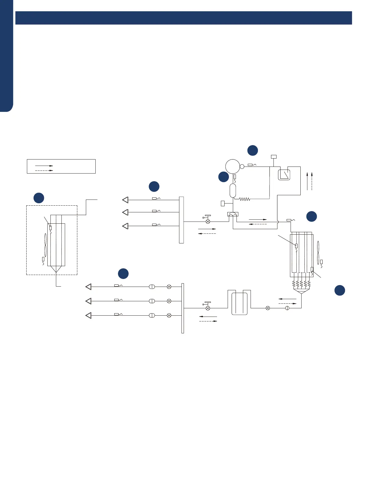
Operations
Comp-
ressor
D
ischarge temp.
●
sensor
Oil
separator
Capillary tube
Ø2.7*Ø1.0*1400
High pressure
switch
4-way valve
Pipe sensor
Toci
Suction temp.
sensor Ts
Low pressure
switch
Accumulator
Gas service valve
Outdoor
heat
exchanger
temp.
sensor
FAN-OUT
Outdoor
ambient
temperature
sensor Ta
Defrost
sensor Td
Distributor
Strainer
EEV O
Receiver
Liquid service valve
5/8
3/8
Unit A liquid pipe temp. sensor Tc2
Strainer
EEV A
Indoor unit A
Unit B liquid pipe temp. sensorTc2
Strainer
EEV B
Indoor unit B
Unit C liquid pipe temp. sensor Tc2
Strainer
EEV C
Indoor unit C
Unit A gas pipe temp. sensor Tc1
Unit
B gas pipe temp.
sensor Tc1
Unit C gas pipe temp. sensor Tc1
Indoor unit A
Indoor unit B
Indoor unit C
4-way valve coil:
OFF
ON
Refrigerant flow in cooling
Refrigerant flow in heating
FAN-IN
Indoor
ambient
temperature
sensor
Indoor
heat
exchanger
temp.
sensor
On a call for heating, the indoor unit will send the room temperature and set-point requirement to the outdoor unit PCB via the
data signal wire path. The data travels from the indoor unit to the outdoor unit via the wire located on terminal 3/C. The indoor
unit louvers will open. The fan will not start until the coil has warmed suciently to avoid cold drafts.
EEVs serving indoor circuits will step to the standard opening. The outdoor EEV opens to a position based upon the outdoor air
temperature.
The 4-way valve will energize and the outdoor fan will start. The compressor starts at a slow speed and will increase based upon
demand. The indoor fan starts after the indoor coil is warm enough to avoid circulating cool air.
With the compressor operating, refrigerant will begin to ow throughout the refrigeration circuit.
The operating frequency of the compressor will be displayed on the Service Monitor Board.
When the compressor starts, hot gas will ow into the oil separator. Oil will be trapped in the separator and returned to the
suction inlet of the compressor via the capillary tube assembly low pressure path.
1
2
3
4
5
6
2
Te
Heating Mode Sequence of Operation
 Loading...