5-104 F60 Feeder Protection System GE Multilin
5.4 SYSTEM SETUP 5 SETTINGS
5
The power system NOMINAL FREQUENCY value is used as a default to set the digital sampling rate if the system frequency
cannot be measured from available signals. This may happen if the signals are not present or are heavily distorted. Before
reverting to the nominal frequency, the frequency tracking algorithm holds the last valid frequency measurement for a safe
period of time while waiting for the signals to reappear or for the distortions to decay.
The phase sequence of the power system is required to properly calculate sequence components and power parameters.
The
PHASE ROTATION setting matches the power system phase sequence. Note that this setting informs the relay of the
actual system phase sequence, either ABC or ACB. CT and VT inputs on the relay, labeled as A, B, and C, must be con-
nected to system phases A, B, and C for correct operation.
The FREQUENCY AND PHASE REFERENCE setting determines which signal source is used (and hence which AC signal) for
phase angle reference. The AC signal used is prioritized based on the AC inputs that are configured for the signal source:
phase voltages takes precedence, followed by auxiliary voltage, then phase currents, and finally ground current.
For three phase selection, phase A is used for angle referencing ( ), while Clarke transformation of the
phase signals is used for frequency metering and tracking ( ) for better performance dur-
ing fault, open pole, and VT and CT fail conditions.
The phase reference and frequency tracking AC signals are selected based upon the Source configuration, regardless of
whether or not a particular signal is actually applied to the relay.
Phase angle of the reference signal always displays zero degrees and all other phase angles are relative to this signal. If
the pre-selected reference signal is not measurable at a given time, the phase angles are not referenced.
The phase angle referencing is done via a phase locked loop, which can synchronize independent UR-series relays if they
have the same AC signal reference. This results in very precise correlation of phase angle indications between different
UR-series relays.
FREQUENCY TRACKING is set to “Disabled” only in unusual circumstances; consult the factory for special variable-
frequency applications.
The frequency tracking feature functions only when the F60 is in the “Programmed” mode. If the F60 is “Not Pro-
grammed”, then metering values are available but can exhibit significant errors.
5.4.3 SIGNAL SOURCES
PATH: SETTINGS SYSTEM SETUP SIGNAL SOURCES SOURCE 1(4)
Identical menus are available for each source. The "SRC 1" text can be replaced by with a user-defined name appropriate
for the associated source.
The first letter in the source identifier represents the module slot position. The number directly following this letter repre-
sents either the first bank of four channels (1, 2, 3, 4) called “1” or the second bank of four channels (5, 6, 7, 8) called “5” in
a particular CT/VT module. See the Introduction to AC Sources section at the beginning of this chapter for details on this
concept.
It is possible to select the sum of all CT combinations. The first channel displayed is the CT to which all others will be
referred. For example, the selection “F1+F5” indicates the sum of each phase from channels “F1” and “F5”, scaled to
whichever CT has the higher ratio. Selecting “None” hides the associated actual values.
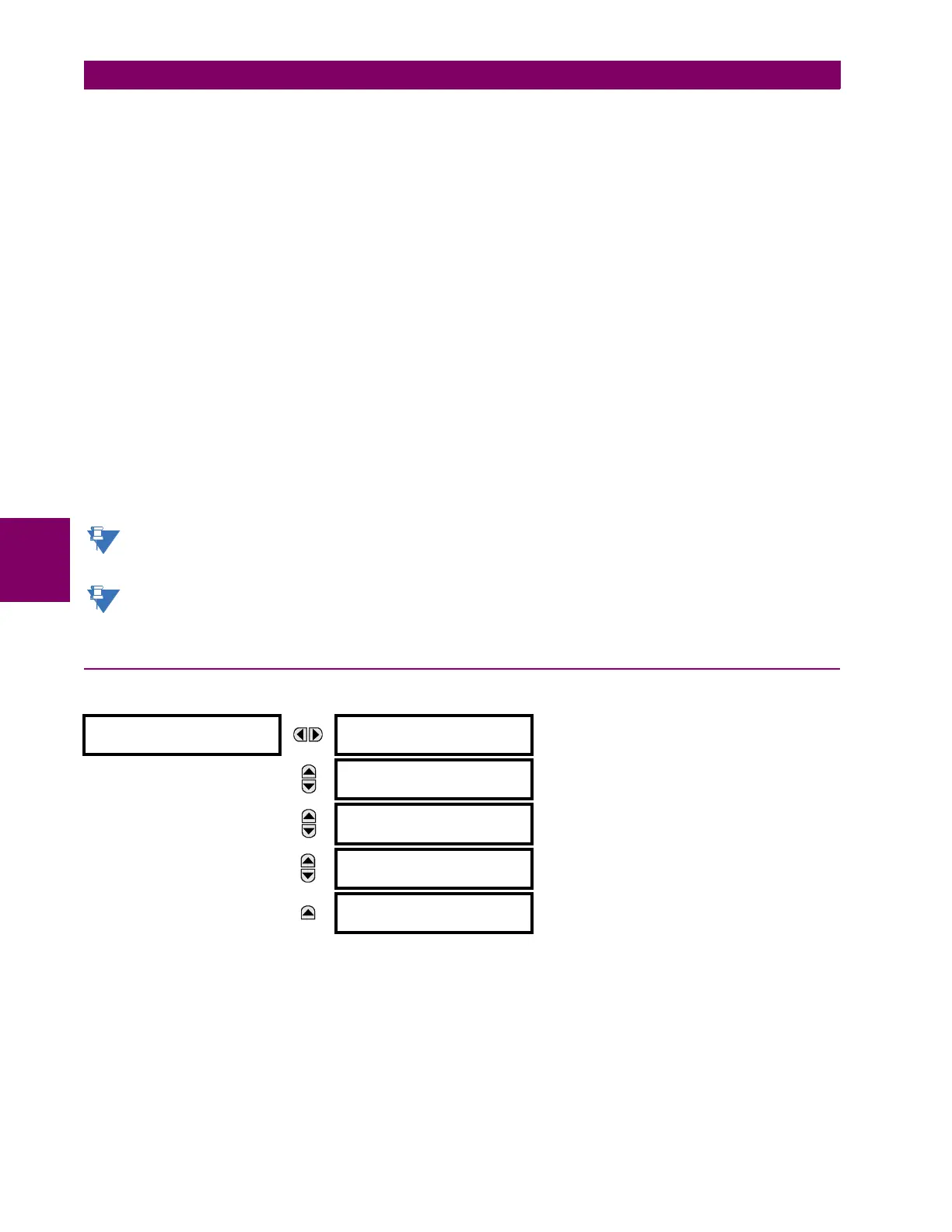
SOURCE 1
SOURCE 1 NAME:
SRC 1
Range: up to six alphanumeric characters
MESSAGE
SOURCE 1 PHASE CT:
None
Range: None, F1, F5, F1+F5,... up to a combination of
any 6 CTs. Only Phase CT inputs are displayed.
MESSAGE
SOURCE 1 GROUND CT:
None
Range: None, F1, F5, F1+F5,... up to a combination of
any 6 CTs. Only Ground CT inputs are displayed.
MESSAGE
SOURCE 1 PHASE VT:
None
Range: None, F5
Only phase voltage inputs will be displayed.
MESSAGE
SOURCE 1 AUX VT:
None
Range: None, F5
Only auxiliary voltage inputs will be displayed.
V
FREQUENCY
2V
A
V
B
– V
C
–()3⁄=

 Loading...


