GE Multilin F60 Feeder Protection System 9-1
9 COMMISSIONING 9.1 TESTING
9
9 COMMISSIONING 9.1TESTING 9.1.1 TESTING UNDERFREQUENCY AND OVERFREQUENCY ELEMENTS
Underfrequency and overfrequency protection requires techniques with subtle testing implications. Whereas most protec-
tion is designed to detect changes from normal to fault conditions that occur virtually instantaneously, power system inertia
requires frequency protection to pickup while the frequency is changing slowly. Frequency measurement is inherently sen-
sitive to noise, making high precision in combination with high speed challenging for both relays and test equipment.
Injection to a particular F60 frequency element must be to its configured source and to the channels the source uses for fre-
quency measurement. For frequency measurement, a source will use the first quantity configured in the following order:
1. Phase voltages
2. Auxiliary voltage
3. Phase currents
4. Ground current
For example, if only auxiliary voltage and phase currents are configured, the source will use the auxiliary voltage, not the
phase voltages or any of the currents.
When phase voltages or phase currents are used, the source applies a filter that rejects the zero-sequence component. As
such, the same signal must not be injected to all three phases, or the injected signal will be completely filtered out. For an
underfrequency element using phase quantities, the phase A signal must be above the
MIN VOLT/AMP setting value. There-
fore, either inject into phase A only, or inject a balanced three-phase signal.
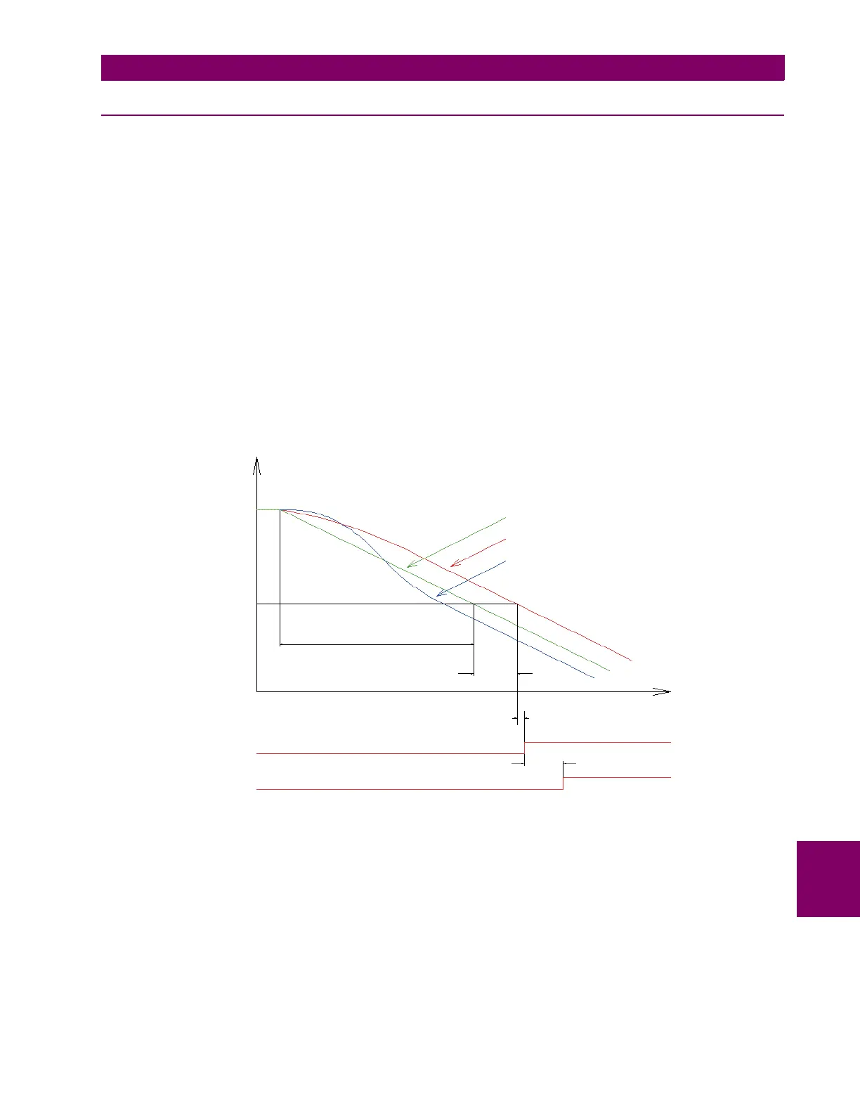
Figure 9–1: TYPICAL UNDERFREQUENCY ELEMENT TEST TIMING
The static accuracy of the frequency threshold may be determined by slowly adjusting the frequency of the injected signal
about the set pickup. If the F60 frequency metering feature is used to determine the injected frequency, the metering accu-
racy should be verified by checking it against a known standard (for example, the power system).
To accurately measure the time delay of a frequency element, a test emulating realistic power system dynamics is required.
The injected frequency should smoothly ramp through the set threshold, with the ramp starting frequency sufficiently out-
side the threshold so the relay becomes conditioned to the trend before operation. For typical interconnected power sys-
tems, the recommended testing ramp rate is 0.20 Hz/s.
Frequency
Pickup
frequency
Relay conditioning time
Injection frequency
Source frequency
Tracking frequency
Source frequency calculation delay
Underfrequency element detection time
Underfrequency element pickup
Underfrequency element operate
set “pickup delay”
Time
831771A1.CDR

 Loading...


