EasyManua.ls Logo

GE F60 User Manual

GE F60
732 pages
To Next Page IconTo Next Page
To Previous Page IconTo Previous Page
Page #288 background imageLoading...
Page #288 background image
5-156 F60 Feeder Protection System GE Multilin
5.5 FLEXLOGIC 5 SETTINGS
5
5.5.2 FLEXLOGIC RULES
When forming a FlexLogic equation, the sequence in the linear array of parameters must follow these general rules:
1. Operands must precede the operator which uses the operands as inputs.
2. Operators have only one output. The output of an operator must be used to create a virtual output if it is to be used as
an input to two or more operators.
3. Assigning the output of an operator to a virtual output terminates the equation.
4. A timer operator (for example, "TIMER 1") or virtual output assignment (for example, " = Virt Op 1") may only be used
once. If this rule is broken, a syntax error will be declared.
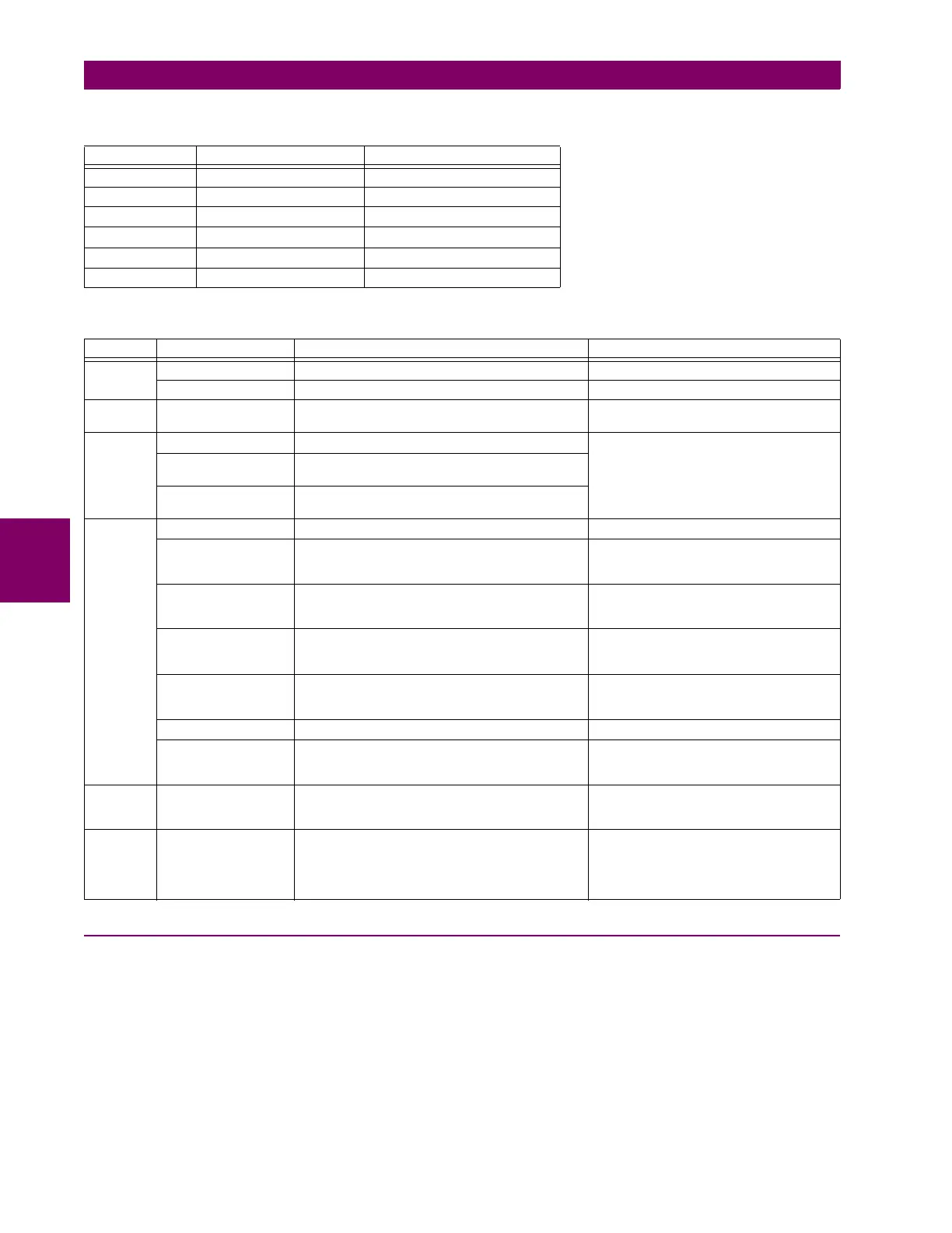
Table 5–19: FLEXLOGIC GATE CHARACTERISTICS
GATES NUMBER OF INPUTS OUTPUT IS ‘1’ (= ON) IF...
NOT 1 input is ‘0’
OR 2 to 16 any input is ‘1’
AND 2 to 16 all inputs are ‘1’
NOR 2 to 16 all inputs are ‘0’
NAND 2 to 16 any input is ‘0’
XOR 2 only one input is ‘1’
Table 5–20: FLEXLOGIC OPERATORS
TYPE SYNTAX DESCRIPTION NOTES
Editor INSERT Insert a parameter in an equation list.
DELETE Delete a parameter from an equation list.
End END The first END encountered signifies the last entry in
the list of processed FlexLogic parameters.
One-shot POSITIVE ONE SHOT One shot that responds to a positive going edge. A ‘one shot’ refers to a single input gate
that generates a pulse in response to an
edge on the input. The output from a ‘one
shot’ is True (positive) for only one pass
through the FlexLogic equation. There is a
maximum of 64 ‘one shots’.
NEGATIVE ONE
SHOT
One shot that responds to a negative going edge.
DUAL ONE SHOT One shot that responds to both the positive and
negative going edges.
Logic
gate
NOT Logical NOT Operates on the previous parameter.
OR(2)
↓
OR(16)
2 input OR gate
↓
16 input OR gate
Operates on the 2 previous parameters.
↓
Operates on the 16 previous parameters.
AND(2)
↓
AND(16)
2 input AND gate
↓
16 input AND gate
Operates on the 2 previous parameters.
↓
Operates on the 16 previous parameters.
NOR(2)
↓
NOR(16)
2 input NOR gate
↓
16 input NOR gate
Operates on the 2 previous parameters.
↓
Operates on the 16 previous parameters.
NAND(2)
↓
NAND(16)
2 input NAND gate
↓
16 input NAND gate
Operates on the 2 previous parameters.
↓
Operates on the 16 previous parameters.
XOR(2) 2 input Exclusive OR gate Operates on the 2 previous parameters.
LATCH (S,R) Latch (set, reset): reset-dominant The parameter preceding LATCH(S,R) is
the reset input. The parameter preceding
the reset input is the set input.
Timer TIMER 1
↓
TIMER 32
Timer set with FlexLogic timer 1 settings.
↓
Timer set with FlexLogic timer 32 settings.
The timer is started by the preceding
parameter. The output of the timer is
TIMER #.
Assign
virtual
output
= Virt Op 1
↓
= Virt Op 96
Assigns previous FlexLogic operand to virtual
output 1.
↓
Assigns previous FlexLogic operand to virtual
output 96.
The virtual output is set by the preceding
parameter

Table of Contents

Question and Answer IconNeed help?

Do you have a question about the GE F60 and is the answer not in the manual?

GE F60 Specifications

General IconGeneral
Frequency50/60 Hz
ManufacturerGE (General Electric)
Communication ProtocolsDNP3, IEC 61850
MountingPanel Mount
DisplayLCD
Power Supply24-250V DC
Current Rating5A
StandardsIEC 60255
Device TypeProtection Relay
Protection FunctionsOvercurrent

Summary

1 GETTING STARTED

1.1 IMPORTANT PROCEDURES

Details essential procedures for initial setup and safe operation of the F60 Feeder Protection System.

1.2 UR OVERVIEW

Provides a general introduction to the UR Series relays, covering hardware and software architecture.

1.3 ENERVISTA UR SETUP SOFTWARE

Covers system requirements, installation, and configuration of the EnerVista UR Setup software for the F60 relay.

1.4 UR HARDWARE

Details the hardware aspects of the UR series relays, including mounting and communication options.

1.5 USING THE RELAY

Explains how to navigate the relay's interface, including keypad usage, menu structure, and basic operations.

2 PRODUCT DESCRIPTION

2.1 INTRODUCTION

Provides an overview of the F60 Feeder Protection System, its features, communication options, and security.

2.2 ORDER CODES

Details the various order codes for the F60 relay, including options for mounting and modules.

2.3 SIGNAL PROCESSING

Explains the signal processing steps within the UR series relays, from analog inputs to digital outputs.

2.4 SPECIFICATIONS

Lists detailed technical specifications for the F60 relay's protection elements, inputs, outputs, and communications.

3 HARDWARE

3.1 DESCRIPTION

Describes the hardware components of the F60 relay, including panel cutout and rear terminal layout.

3.2 WIRING

Provides typical wiring diagrams and details for various modules, including CT/VT, process bus, and direct I/O.

3.3 DIRECT INPUT/OUTPUT COMMUNICATIONS

Explains the configuration and operation of direct I/O communication channels for UR-series relays.

4 HUMAN INTERFACES

4.1 ENERVISTA UR SETUP SOFTWARE INTERFACE

Details the graphical user interface of the EnerVista UR Setup software, covering device engagement, settings files, and firmware upgrades.

4.2 FACEPLATE INTERFACE

Describes the relay's front panel interface, including enhanced and standard faceplate layouts, LED indicators, and keypad operations.

5 SETTINGS

5.1 OVERVIEW

Provides an overview of the settings menu, introducing elements, AC sources, and their configuration.

5.2 PRODUCT SETUP

Details various product setup configurations, including security, display properties, communications, and system settings.

5.3 REMOTE RESOURCES

Explains how to configure remote resources, specifically for HardFiber system integration.

5.4 SYSTEM SETUP

Covers system setup configurations, including AC inputs, power system, signal sources, breakers, and communications.

5.5 FLEXLOGIC

Details the FlexLogic feature, including its introduction, rules, examples, and parameters.

5.6 GROUPED ELEMENTS

Explains grouped elements, setting groups, and specific protection elements like load encroachment, phase/neutral/ground current, and voltage elements.

5.7 CONTROL ELEMENTS

Describes control elements such as trip bus, setting groups, selector switch, underfrequency, overfrequency, and breaker control logic.

6 ACTUAL VALUES

6.1 OVERVIEW

Provides an overview of the actual values menu, listing status, metering, records, and product information.

6.2 STATUS

Details the status of various inputs and outputs, including contact inputs, virtual inputs, remote devices, and communication statuses.

6.3 METERING

Explains metering conventions and displays values for sources, phase current, ground current, voltage, power, energy, and harmonics.

6.4 RECORDS

Covers records available in the relay, including fault reports, event records, oscillography, data logger, PMU records, and breaker maintenance.

6.5 PRODUCT INFORMATION

Provides information about the relay's model, order code, firmware revisions, and manufacturing details.

7 COMMANDS AND TARGETS

7.1 COMMANDS

Details commands available for relay operations, including clear records, set date/time, relay maintenance, and security settings.

8 THEORY OF OPERATION

8.1 HIGH-IMPEDANCE (HI-Z) FAULT DETECTION

Explains the algorithms used for high-impedance fault detection, including arcing and downed conductor identification.

8.2 FAULT LOCATOR

Describes the fault location algorithm, including fault type determination and calculations for fault distance.

10 MAINTENANCE

10.1 MODULES

Provides instructions for the withdrawal and insertion of relay modules.

10.2 BATTERIES

Details procedures for replacing the real-time clock battery for different power supply modules.

10.3 UNINSTALL AND CLEAR FILES AND DATA

Explains how to decommission the unit and clear files, including settings files and COMTRADE data.

10.4 REPAIRS

Outlines the process for returning a device to the factory for repair, including contact information and shipping instructions.

10.5 STORAGE

Provides guidelines for storing the unit, including environmental conditions and powering up stored units.

10.6 DISPOSAL

Describes the disposal requirements for the unit and its battery, including recycling information.

APPENDIX A FLEXANALOG AND FLEXINTEGER PARAMETERS

A.1 PARAMETER LISTS

Lists available FlexAnalog parameters, including address, name, units, and description.

APPENDIX B MODBUS COMMUNICATIONS

B.1 MODBUS RTU PROTOCOL

Details the Modbus RTU protocol, including introduction, physical layer, data link layer, and CRC algorithm.

B.2 MODBUS FUNCTION CODES

Lists and describes the supported Modbus function codes for relay operations.

B.3 FILE TRANSFERS

Explains how to obtain relay files via Modbus, including COMTRADE, oscillography, and data logger files.

B.4 MEMORY MAPPING

Provides a detailed Modbus memory map, listing registers, ranges, units, and default values.

APPENDIX C IEC 61850 COMMUNICATION

C.1 OVERVIEW

Introduces the IEC 61850 standard, its communication profiles, and file transfer methods.

C.2 SERVER DATA ORGANIZATION

Describes the IEC 61850 data organization, including logical nodes, digital status, control values, and analog values.

C.5 IEC 61850 IMPLEMENTATION VIA ENERVISTA UR SETUP

Explains how to configure the F60 for IEC 61850 using EnerVista UR Setup software, including ICD and SCD file creation.

C.6 ACSI CONFORMANCE

Details the ACSI conformance statements for basic, models, and services.

C.7 LOGICAL NODES

Lists the IEC 61850 logical nodes supported by the UR-series relays.

APPENDIX D IEC 60870-5-103 COMMUNICATION

D.1 IEC 60870-5-103

Provides an overview of the IEC 60870-5-103 protocol and calculations for transmitting measurands.

D.1.3 INTEROPERABILITY DOCUMENT

Details the interoperability document for IEC 60870-5-103, covering physical layer, link layer, and application layer.

APPENDIX E IEC 60870-5-104 COMMUNICATION

E.1 IEC 60870-5-104

Covers the IEC 60870-5-104 standard, including interoperability document and point lists.

APPENDIX F DNP POINT LISTS

F.1 DEVICE PROFILE DOCUMENT

Provides the DNP v3.00 device profile document, detailing supported objects, functions, and parameters.

F.2 DNP POINT LISTS

Lists DNP binary input points and binary and control relay output points.

APPENDIX G RADIUS SERVER CONFIGURATION

G.1 RADIUS SERVER CONFIGURATION

Provides a step-by-step example for setting up a simple RADIUS server.

APPENDIX H CHANGE NOTES

H.1 CHANGE NOTES

Details the revision history and major updates made to the F60 manual across different versions.

H.2 ABBREVIATIONS

Provides a list of standard abbreviations used in the document.

H.3 WARRANTY

Outlines the GE Multilin warranty terms and conditions for products.

Related product manuals