EasyManuals Logo
Home>GE>Medical Equipment>LOGIQ S8 Vet

GE LOGIQ S8 Vet User Manual

GE LOGIQ S8 Vet
418 pages
To Next Page IconTo Next Page
To Previous Page IconTo Previous Page
Page #252 background imageLoading...
Page #252 background image
GE HEALTHCARE
DIRECTION 5394227, 12 LOGIQ S8/LOGIQ E8 SERVICE MANUAL
5 - 26 Section 5-9 - Air Flow Distribution
Section 5-9
Air Flow Distribution
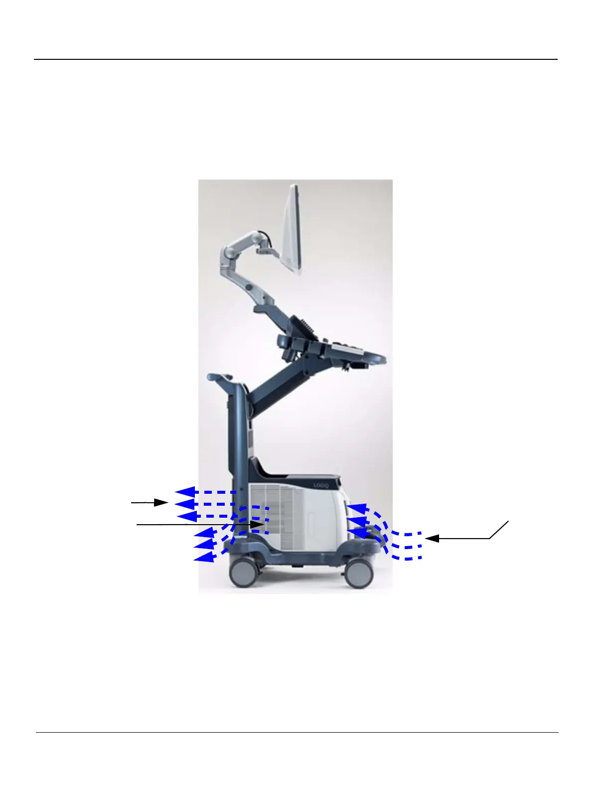
5-9-1 Air Flow Distribution
Through the filter grid on the front of the system, air flow into the LOGIQ S8.
By means of the 1 FAN, air is blown through the nest-box, and the warm air exits the system through
holes in the left side panel and rear of the system.
Figure 5-17 Air Inlet/Outlet
Main Air
inlet
(Filter grid)
Main Air
Outlet
(Rear)
(Side)

Table of Contents

Questions and Answers:

Question and Answer IconNeed help?

Do you have a question about the GE LOGIQ S8 Vet and is the answer not in the manual?

GE LOGIQ S8 Vet Specifications

General IconGeneral
BrandGE
ModelLOGIQ S8 Vet
CategoryMedical Equipment
LanguageEnglish

Related product manuals