C.11
M-PACT Plus
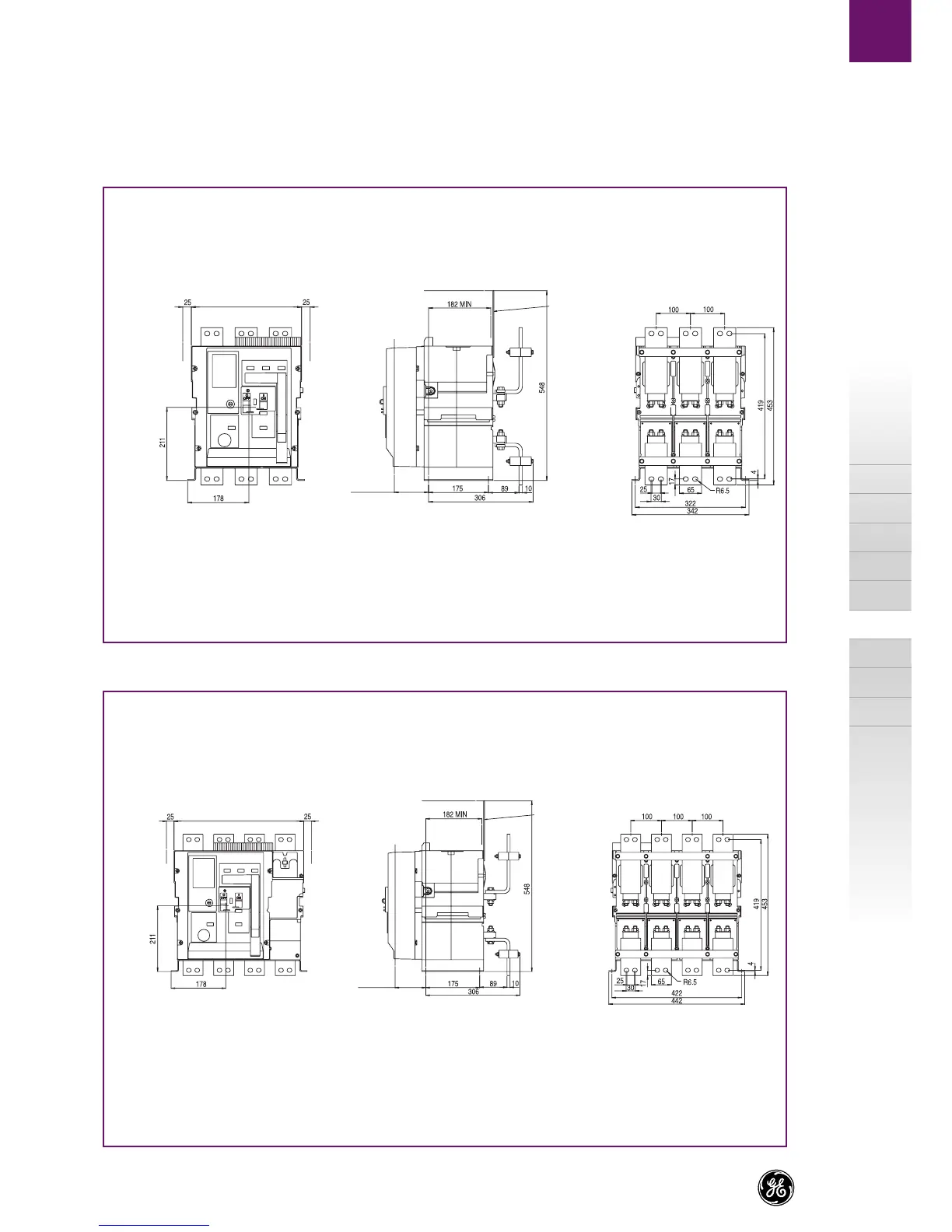
Dimensional drawings
A
B
C
X
Front access connection
Fixed pattern
Type S, N - 3 pole - Frame size 1, ln = 400A to 1600A
Type S, N - 4 pole - Frame size 1, ln = 400A to 1600A
Center line of
operating panel
Center line of
operating panel
Insulated metal
or insulated sheet
(customer supplied)
Minimum space to earth metal
and for arc chute removal
100 to door
Minimum clearance
to breaker side
Copperwork must be supported within 200 mm of breaker
connections-busbars or cables. All connections to be tightened to 50Nm.
Center line of
operating panel
Center line of
operating panel
Insulated metal
or insulated sheet
(customer supplied)
Minimum space to earth metal
and for arc chute removal
100 to door
Minimum clearance
to breaker side
Copperwork must be supported within 200 mm of breaker
connections-busbars or cables. All connections to be tightened to 50Nm.
 Loading...