C.20
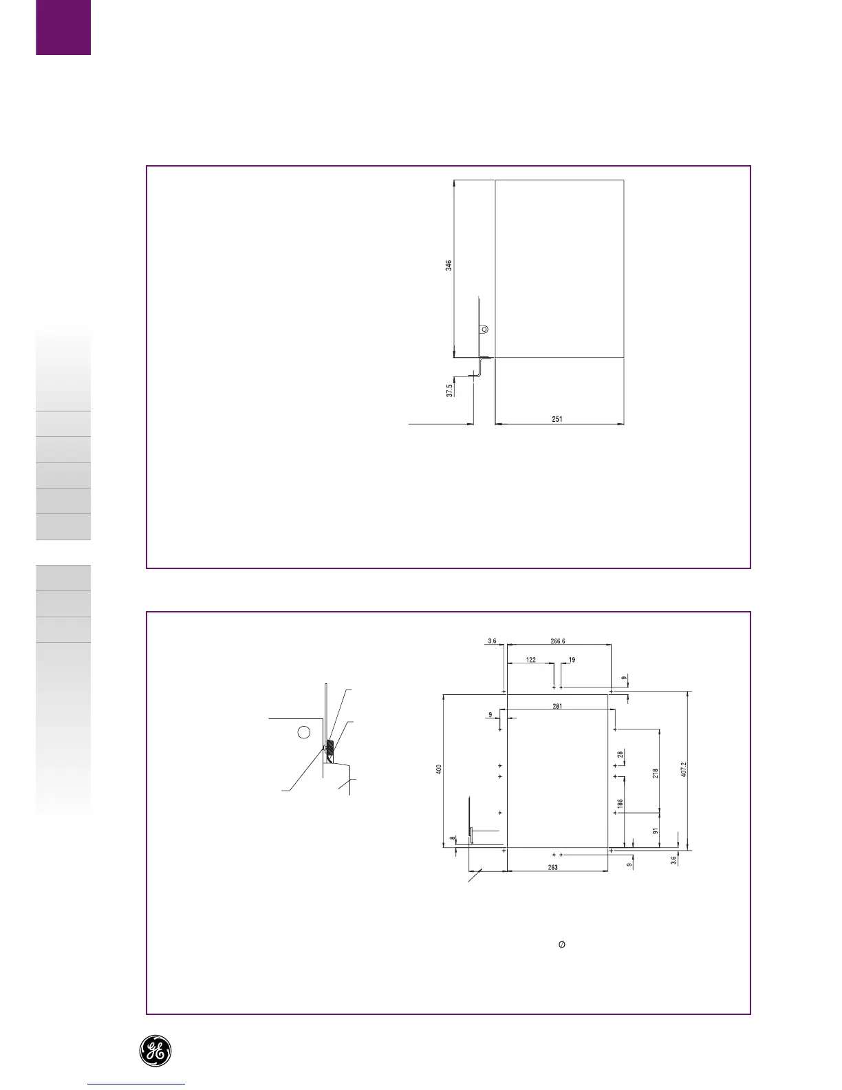
Dimensional drawings
A
B
C
X
M-PACT Plus
Door cut-outs
Fixed pattern - Facia cut-out
Withdrawable pattern - Cubicle door/panel
Frame 1 = 42.5
Frame 2 = 102.5
The cut-out dimensions shown above give
an approximate nominal clearance of 30mm around
ACB fascia. These sizes are for guidance
and can be scaled if different aperture
is required.
Escutcheon
(LLA11PD055)
Escutcheon seal
(LLA11RS001)
ACB facia
16 off 3.0×6
Self tapping screws
Frame 1 - Up to 2500A max.= 40
Frame 2 - Up to 4000A max.= 100
Datum for 16 off 4 holes in door / panel
- bottom left hand comer of cassette
viewed from front.
 Loading...