SecoGear – Installation, Operation and Maintenance Manual 20 of 56
In addition, a grounding device is provided, which contacts the
fuses after they are disconnected, effectively removing any static
charge from the fuses, reference IS Field Engineer’s Manual
EM9370, appendix section 25 & 26 for proper discharge of static
charges prior to removal. Once properly discharged, the fuses
may be safely removed and replaced. The disconnecting devices
are capable of interrupting transformer magnetizing current, but
should not be used to interrupt load current.
Mechanical or key interlocks are applied to prevent operating
the disconnect device and withdrawing the tray while the load is
connected. This is generally accomplished by interlocking so that
the transformer secondary circuit breaker must be locked in the
open position before the disconnecting device can be connected
or disconnected. Current-limiting fuse and control power
transformer rollouts are located in auxiliary compartments.
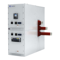
Figure 3-12: Fuses-only Tray
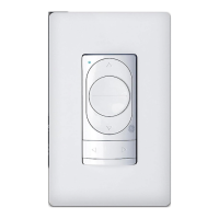
Figure 3-13: CPT with Fuses Tray
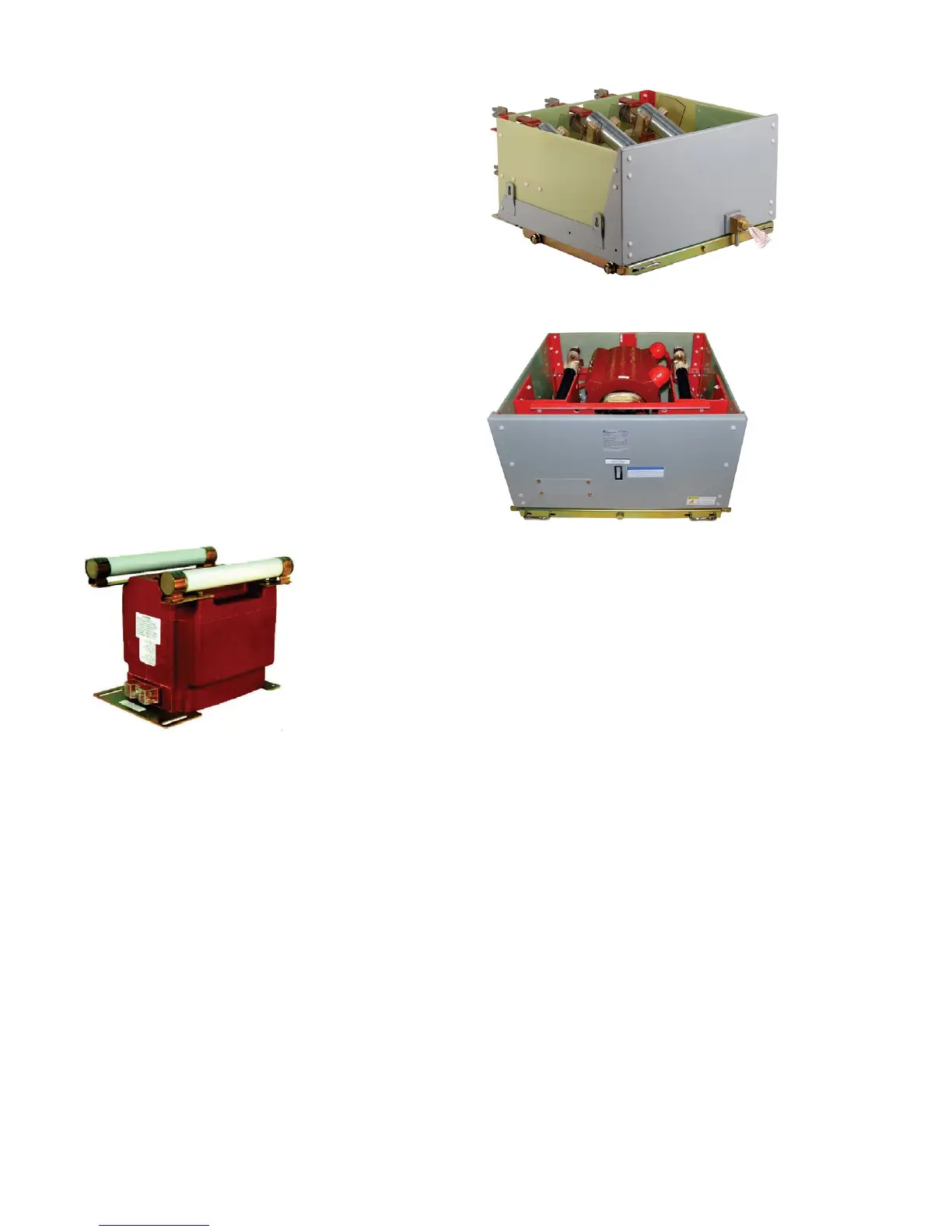
Voltage Transformers
Voltage transformers are located in an auxiliary compartment.
Up to three transformers can be mounted on a movable tray
equipped with primary and secondary disconnecting devices.
When the voltage transformers are disconnected, they are at a
safe strike distance from all live parts of the switchgear.
In addition, a grounding device is provided, which contacts
the fuses when the voltage transformers are disconnected,
effectively discharging the transformers, reference IS Field
Engineer’s Manual EM9370, appendix section 25 & 26 for
proper discharge of static charges prior to removal. Once
properly discharged, the transformer fuses may be safely
removed and replaced. An auxiliary compartment shutter
will isolate the primary disconnect when the rollout is fully
withdrawn from the cell. An insulated barrier mounted at the
rear of the carriage moves with the carriage to a position in
front of the stationary part of the primary disconnect device,
providing a safe striking distance from all live parts.
Auxiliary Compartments
Figure 3-11: Voltage Transformers
Control Power Transformers and Fuse Trays
Current-limiting fuses with high interrupting ratings are
sometimes used in metal-clad switchgear to protect small
transformers or circuits where circuit breakers cannot be
economically or functionally justified. The fuses are mounted
in a movable tray equipped with primary and secondary
disconnecting devices.
Single phase control power transformers up to 15 kVA and their
secondary circuit breaker are mounted on the tray with the
primary fuses (Figure 3-13). Larger control power transformers,
up to 75 kVA (single phase) or 45 kVA (three phase), are located
in the cable compartment behind their associated fuse tray, and
their secondary circuit breaker is located behind a cover on the
upper cable compartment. When the fuses are disconnected,
they are at a safe strike distance from all live parts of the
switchgear. The fuse only tray is shown in Figure 3-12.
 Loading...