SecoGear – Installation, Operation and Maintenance Manual 34 of 56
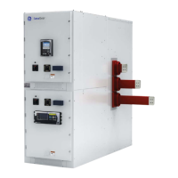
Figure 4-26: Ground Bus – Rear View
Figure 4-25: Ground Bus – Plan View
Table 4-9 indicates torque values to be used for tightening the
fasteners indicated in these documents.
Recommended Torque Values
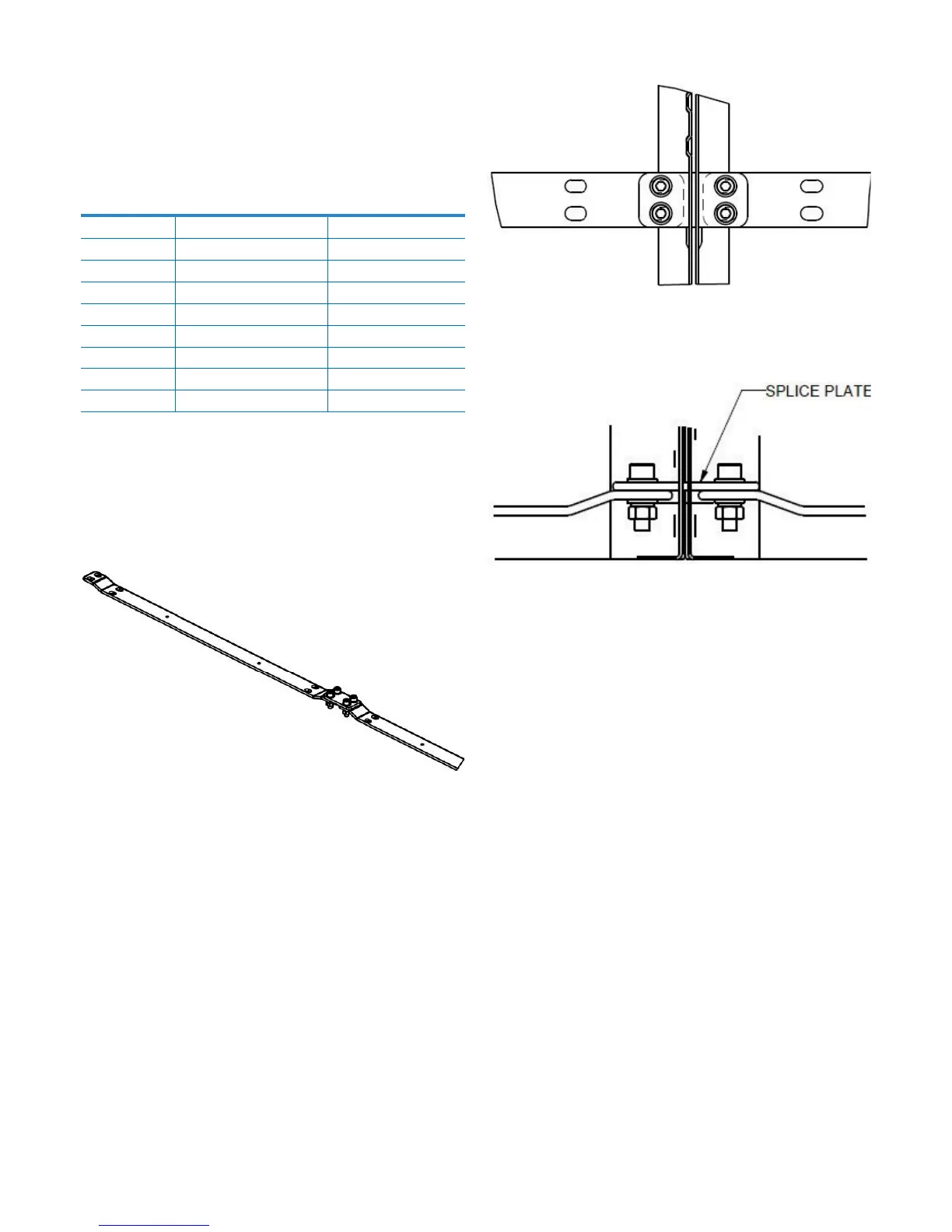
Figure 4-24: Typical Ground Bus
Ground bus splice and hardware are typically shipped assembled
at both sides of adjacent shipping packages.
Ground Bus Installation
Table 4-9: Recommended Torque Limits
BOLT SIZE BOLT TORQUE (N-M) BOLT TORQUE (FT-LBS)
M4 3
2.2
M5 5.9
4.4
M6 10
7.4
M8 26
19.2
M10 50
36.9
M12 86
63.4
M16 200
147.5
M20 300
221.3
 Loading...