SecoGear – Installation, Operation and Maintenance Manual 49 of 56
Replacing Current Transformers (CTS)
The CTs are mounted in the circuit breaker compartment. To
access the CT assembly, de-energize SecoGear, open the front
door, and remove the SecoVac VCB.
1. Prepare the CT for mounting by verifying the following items
before proceeding:
• Ratio
• Polarity
• Category number
• Orientation per line diagram
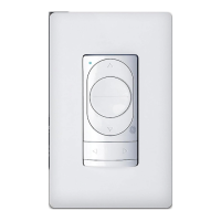
2. Carefully raise and position the CT into the circuit
breaker compartment.
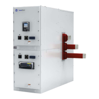
3. Push the CT onto the spout until it is flush with the rear
of the assembly (Figure 9-2). Repeat for any additional CTs.
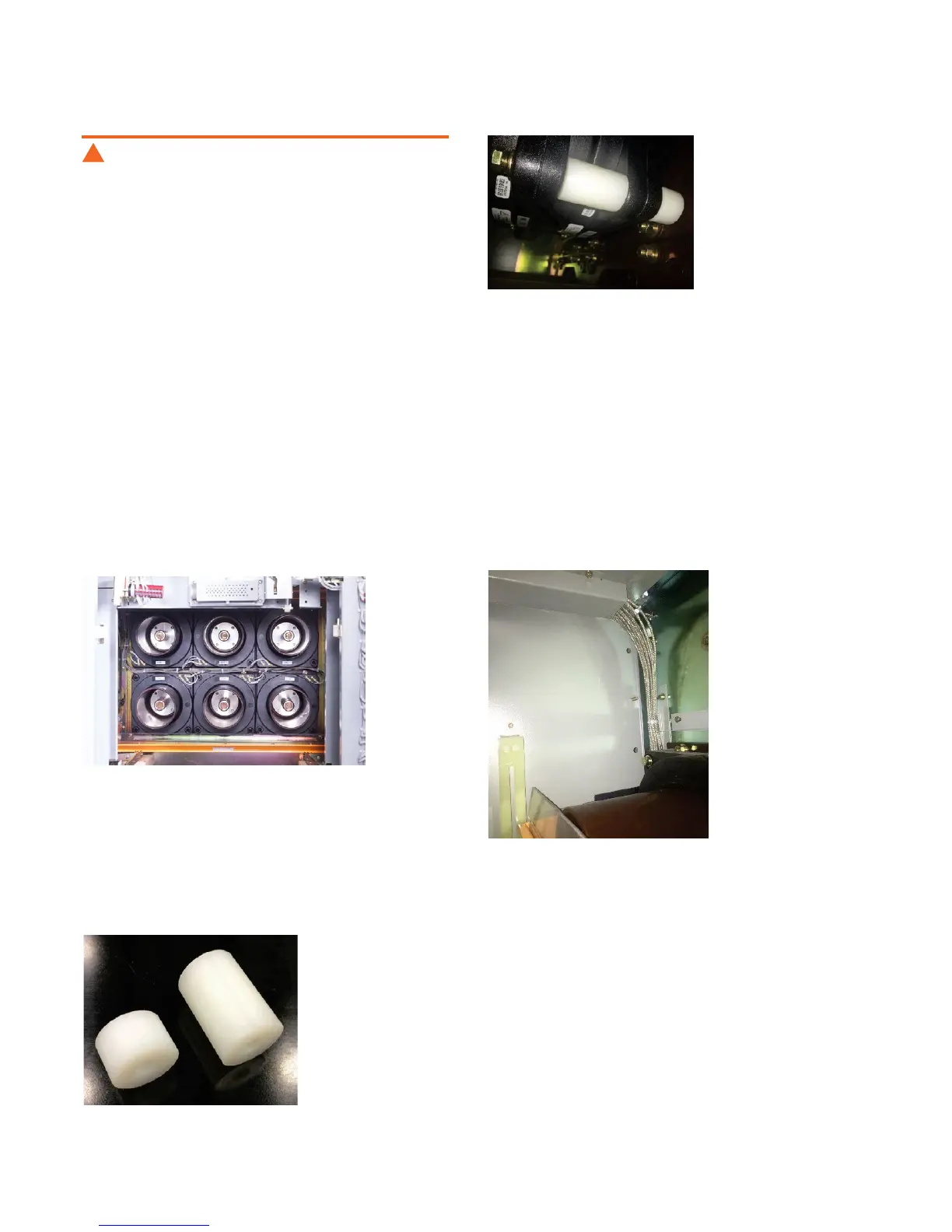
4. Install spacers behind CTs (Figure 9-4). Apply 7/8” spacers to
single CT modules; apply 7/8” and 2” spacers (Figure 9-3) to
piggyback CT modules.
5. Secure CTs by installing bolts from the front, torque to
8 ft.-lbs [10.85 Nm].
Figure 9-2: CTs Mounted in Compartment
Figure 9-3: CT Spacers, 7/8” (left) and 2” (right)
Figure 9-4: CT Spacers Installed
Equipment must be de-energized before beginning any
maintenance work to prevent electrical shock.
WARNING
!
Wire the CTs
1. Remove the wire ties from the CT wire harness, tape the
harness edging, and route the wires through the upper wire
channel/trough. Install the CT wire harness (Figure 9-5) to
each CT individually.
Figure 9-5: CT Wire Harness in Compartment
 Loading...