SecoGear – Installation, Operation and Maintenance Manual 24 of 56
4. Installation
This section contains complete instructions for installing GE
SecoGear metal-clad switchgear for 5kV – 15kV IEEE medium
voltage applications.
Personnel installing this equipment must be thoroughly
familiar with this instruction manual and all articles of
the National Electrical Code applicable to the installation
of this switchgear. In addition, all installation drawings,
both mechanical and electrical, must be understood and
strictly followed to prevent damage to the switchgear
or equipment being protected by the switchgear.
CAUTION
Before installation work is started, it is important to review
all of the drawings provided, including the GE equipment
arrangement drawings, site installation drawings,
elementary and remote connection drawings, mechanical
connection drawings, and the summary of equipment list.
NOTICE
In general, the location of the switchgear equipment
is determined during the equipment’s specification or
procurement. Indoor locations within buildings impose certain
requirements that must be met so that the switchgear may
operate efficiently with a minimum of maintenance.
In locating the switchgear, adequate aisle space must be
provided at the front and rear of the equipment to ensure
proper ventilation of the equipment and to allow service and
Site Location
Recessed steel channels for supporting the equipment are
recommended. However, mounting the indoor switchgear
directly on a smooth, level floor is allowable. The foundation
must be flat and level in all planes, perpendicular on both axes
within 0.25 in. (6.35 mm) over a 10 ft. (3048 mm) span.
The embedded floor channel requirements are as follows:
1. Each floor channel shall be level over its entire length, and
floor channels shall be level with each other. This is critical
to prevent distortion of the equipment and to ensure proper
mechanical and electrical connections between shipping
splits and close-coupled equipment.
2. The finished floor shall be slightly pitched away from the
mounting channels. Ensure that the pitch does not exceed flat
and level requirements.
3. The finished floor shall not be higher than the channels.
4. When bolting to floor channels, floor channels must be drilled
and tapped. (Weld nuts may be welded inside of the channels.)
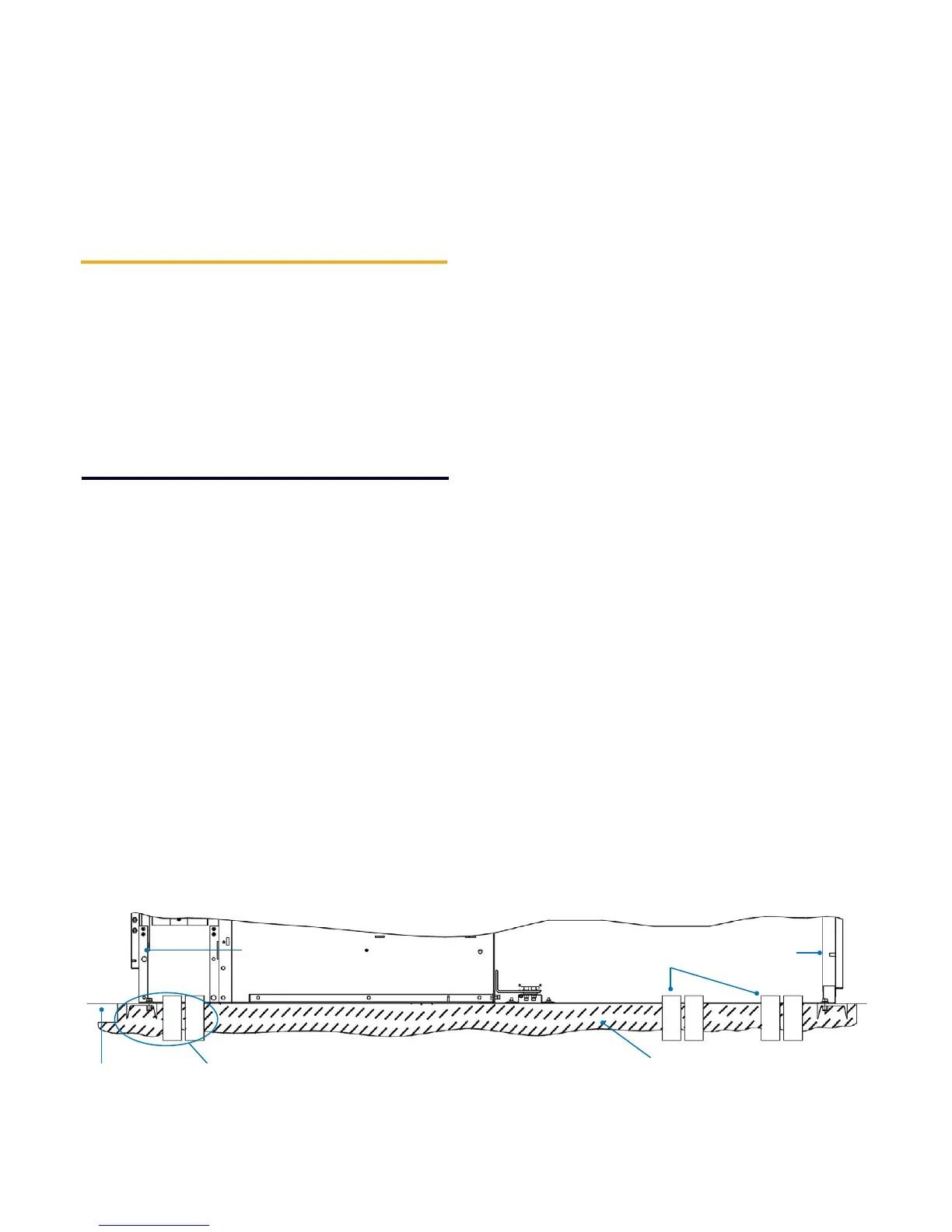
5. Conduit penetrations shall not be greater than 1 in. above the
finished floor. See GE drawing 8PVA005501 (summarized in
Figure 4-1) for anchoring details.
Foundation Requirements
Figure 4-1: SecoGear Installation Drawing – Indoor Anchoring Method
Finished Floor
(Even & Level)
SecoGear
Front Door
Primary
Conduit Leads
SecoGear
Rear Door
Concrete
Foundation
Anchoring Detail
in Figure 4-2
maintenance of the equipment with the front and rear doors
open. The recommended aisle space is shown on the floor plan
supplied with the equipment drawings.
The switchgear equipment should be placed in an area where
clean, dry air is free to circulate around and above it. Since air
is taken into the equipment at the bottom of each section and
exhausted at the top, a location with good airflow must be
provided for efficient operation. A minimum of 30 in. of clear
space above the equipment is recommended.
 Loading...