SecoGear – Installation, Operation and Maintenance Manual 25 of 56
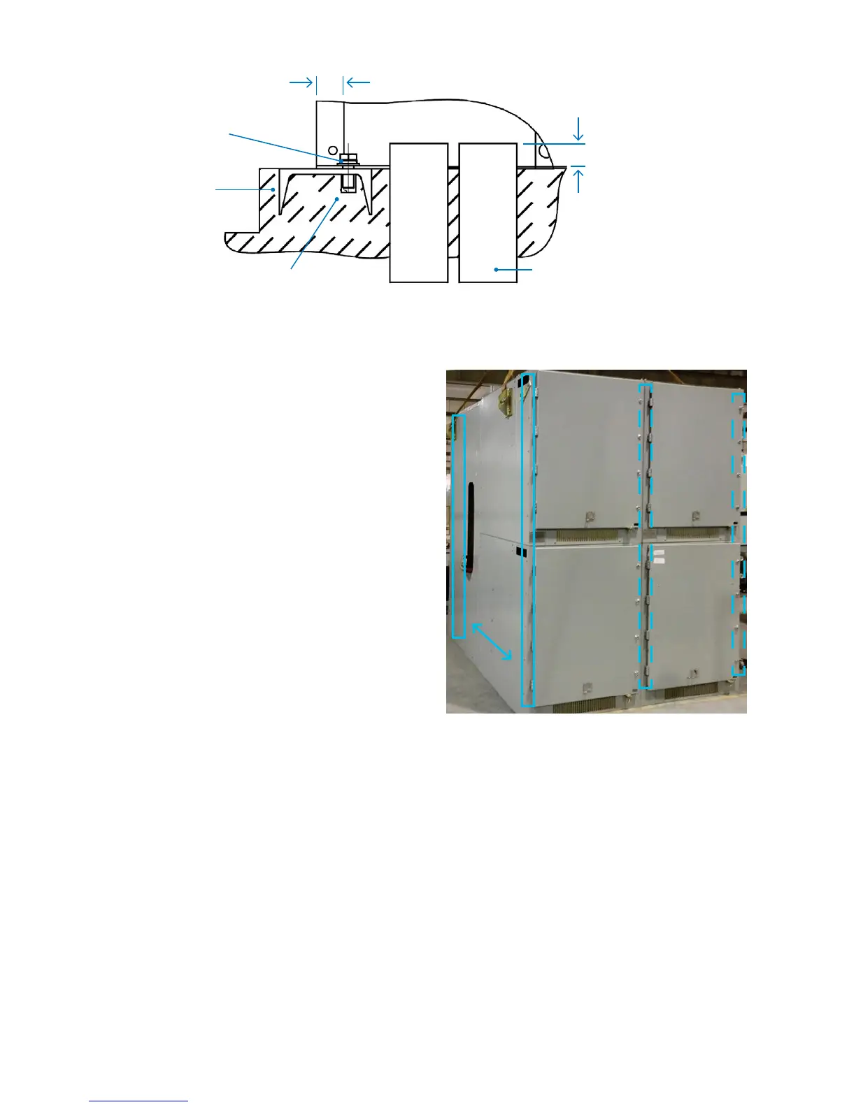
Figure 4-2: SecoGear Primary Indoor Anchoring Method
Figure 4-3: Lineup Shown Assembled
Before assembling SecoGear shipping sections, all components
should be available at the site location. This will facilitate
component identification as well as installation. The foundation
should be prepared in accordance with the instructions in
“Foundation Requirements” and all embedded conduits installed
and capped.
For each lineup, the assembly procedure involves
1. Bolting side-by-side sections together.
2. Inserting main bus and bus ties, and bolting them
between sections.
3. Installing the left and right end trim covers.
4. Interconnecting the wires between the shipping splits.
5. Taping special bus joints, and taping or booting cable
terminations to insulate them.
Assembling Shipping Sections
Adjacent
Sections
Left End
Covers
Right
End Cover
2Ø 0.709 in (18.0 mm) Holes
for M12 [0.5 in] Anchor
Bolts, Front & Rear
1.38 in (35.05 mm)
1.0 in (25.4 mm) max.
Embedded Channel
C5 x 6.7# min.
Conduit Leads Clearance Space
 Loading...