SecoGear – Installation, Operation and Maintenance Manual 26 of 56
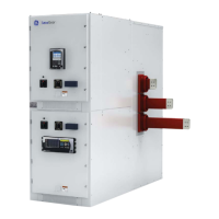
Figure 4-4: Lift Plugs in Position
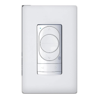
Figure 4-5: Position Wires for Clearance
Once the sections have been moved to the foundation, first
remove the lift plugs from the sides (two per stack per side),
as shown in Figure 4-4.
Next, tuck the interconnect wire (Figure 4-5) into the module
prior to pushing stacks together.
Now, the sections can be pushed to their final positions.
All switchgear sections are bolted together through removable
weld-nut plates located inside the front and rear doors (see
Figure 4-6). Only one nut plate is required per joining section, so
the middle section may have none attached from the factory.
In the front of the modules (Figure 4-5), insert bolts from the
right stack into the nut strip on the left stack. Install five M10 x
25 bolts per module, 10 bolts per stack (torque to 19.2 ft.-lbs.
[26 Nm]).
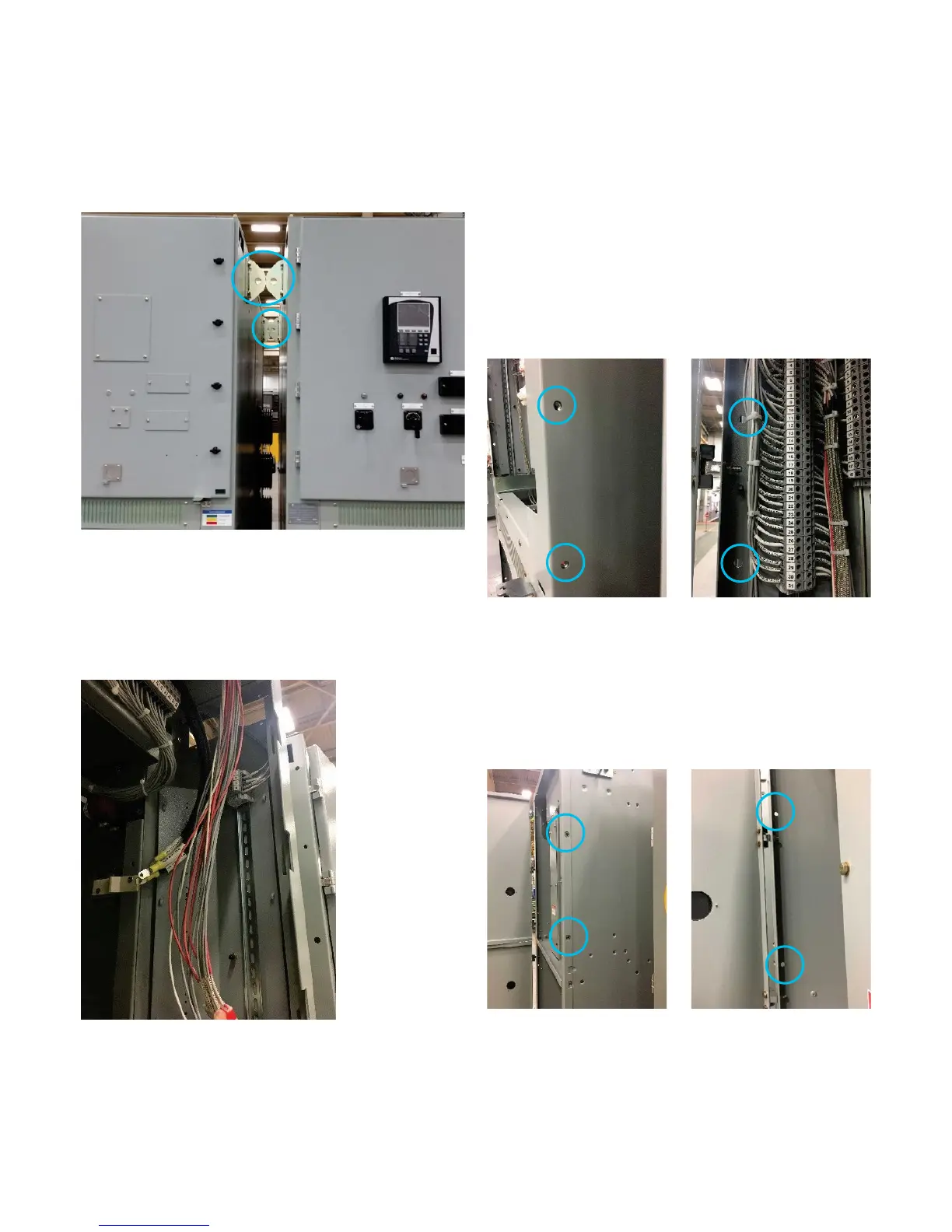
Finally, in the rear compartment (Figure 4-7) insert bolts from the
left stack into the clinch nuts on the right stack. Install six bolts
per stack (torque to 19.2 ft.-lbs. [26 Nm]).
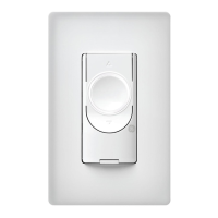
Bolting Sections Together
Figure 4-7: Rear Bolt Locations (left and right)
Figure 4-6: Front Bolt Locations (left and right)
 Loading...