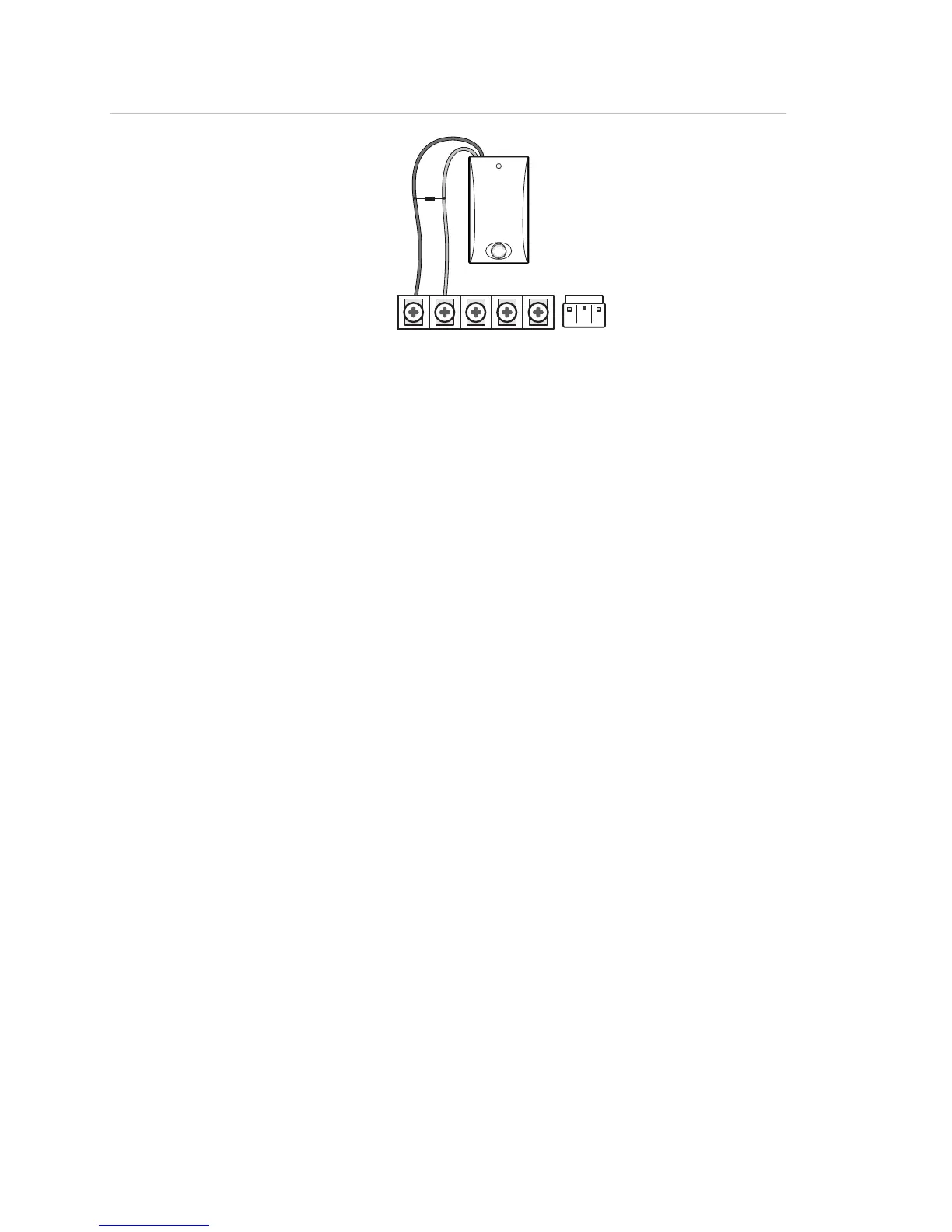
Figure 5: Hardwired interior siren with supervision
1234
5
1 HW1 I/O
2 HW1&2 DC out
4.7 kohm resistor
(located at siren)
Black
Red
Exterior sirens
For an exterior siren, reprogram HW1 to Option 6. See Wiring diagram.
Hardwired contacts
To set up HW1 I/O and/or HW2 for hardwired contacts, make the required
connections described below, and then proceed to “Programming” on page 21 to add
(learn) them into panel memory.
You can connect hardwired reed switches (normally closed loop only) to HW1 I/O (if
not being used for a hardwired siren) and/or HW2 in.
Note: Connect only normally closed (NC) reed switches to HW1 I/O and/or HW2 in.
Other types of hardwired detectors should not be used.
The total resistance of the wired loop must not exceed 3 ohms. This allows you to use
up to 200 ft. (61 m) of two-conductor, 22-gauge stranded wire.
Connect hardwired reed switches to the panel using a 47-kohm resistor (not a 4.7-
kohm resistor) as shown in
Figure 6 on page 17. The resistor must be connected at
the last switch in the circuit.
16 Simon XT Installation Manual
 Loading...