3 • FUNCTIONS
This section describes the use and functions of the displays, lighted indicators and buttons making up the 2500
controller operator interface.
It therefore contains essential information for correct programming and configuration of the controllers.
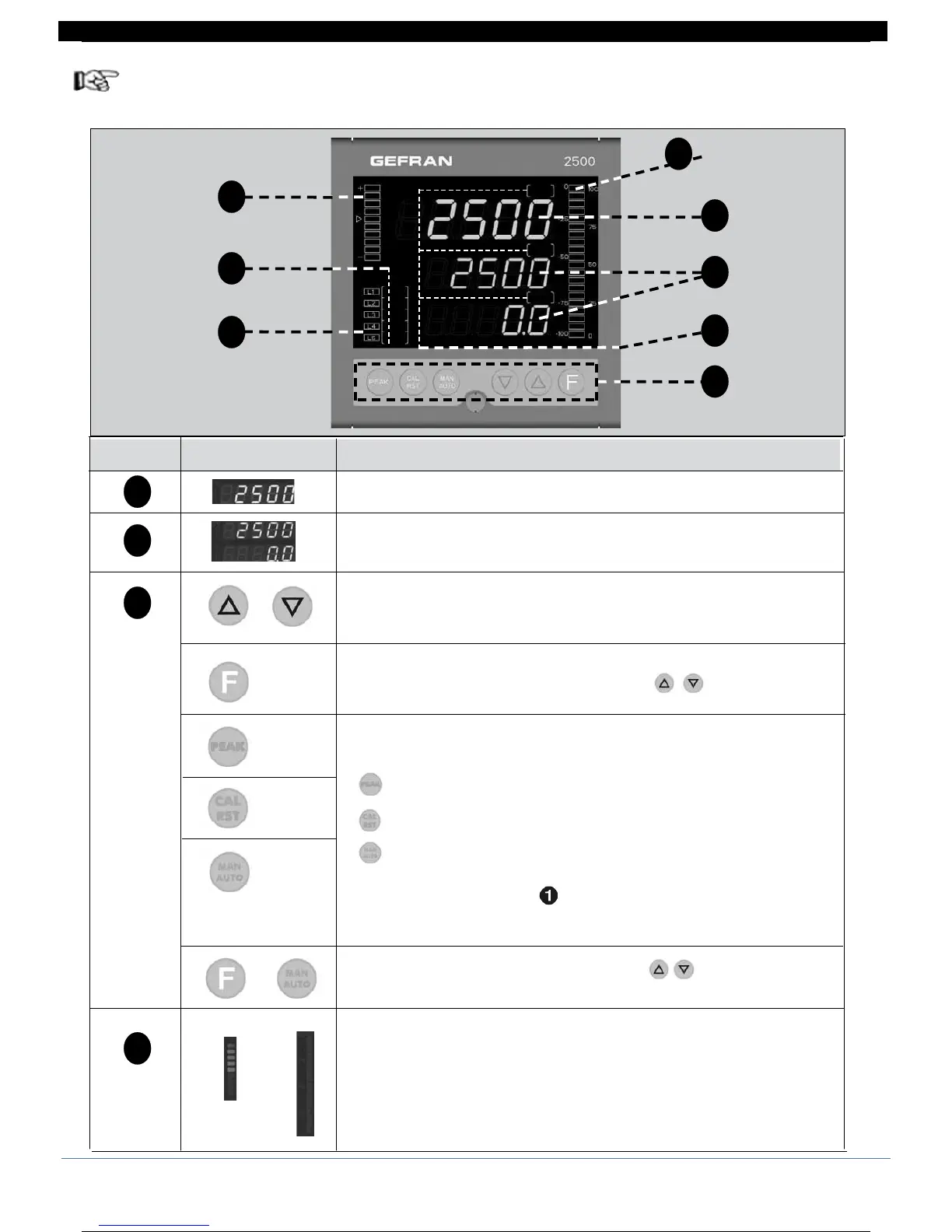
Operator interface
1
2
3
4
5
6
6
4
PV : Shows the process variable and error codes
SV :
Shows the setpoint value (default) or the value of the parameter indicated in F
F : Shows the control output value (default), menus and parameters
identification, the symbol of the parameter whose value is displayed in SV
Raises/Lowers the value of the parameter displayed in SV until the max/min value
is reached.
When kept pushed: progressively increases the raise/lower speed of the value
displayed in SV.
Lets you navigate the controller menus and parameters.
Confirms the value of the current (or modified by ) parameter and
selects the next parameter.
Buttons with configurable function: with standard configuration, switches controller
function
activation maximum peak input IN1
check calibration strain-gauge input IN1
MANUAL/AUTOMATIC
Active only when the display shows the process variable.
(for configuration, see paramete BVT1, BVT2, BVT3 on KRD menu)
Confirms the value of the current (or modified by ) parameter and selects
the preceding parameter.
Bargraph:
bargraph 1: indicates deviation DEV with scale ±10%
bargraph 2: indicates % value of control output
(for configuration, see parameter brG)
ID Symbol Function
+
brg 1
brg 2
SV
F
1
2
3
4
20 80291G_MHW_2500_08-2010_ENG
20 / 77

 Loading...


