2 • INSTALLATION AND CONNECTION
This section contains the instructions necessary for
correct installation of the 2500 controllers into the
machine control panel or the host system and for
correct connection of the controller power supply,
inputs, outputs and interfaces.
Before proceeding with installation read the
following warnings carefully!
Remember that lack of observation of these war-
nings could lead to problems of electrical safety
and electromagnetic compatibility, as well as
invalidating the warranty.
Electrical power supply
• thecontrollerisNOTequippedwithanOn/Offswitch:the
user must provide a two-phase disconnecting switch that
conforms to the required safety standards (CE marking), to
cut off the power supply upstream of the controller.
The switch must be located in the immediate vicinity of the
controller and must be within easy reach of the operator.
One switch may control more than one controller.
• ifthecontrollerisconnectedtoNOTisolatedelectrical
equipment (e.g. thermocouples), the earth connection
must be made with a specific conductor to prevent the
connection itself from coming directly through the
machine structure.
• ifthecontrollerisusedinapplicationswithriskofdamage
to persons, machinery or materials, it is essential to
connect it up to auxiliary alarm equipment. It is advisable
to make sure that alarm signals are also triggered during
normal operation.
The controller must NOT be installed in flammable or
explosive environments; it may be connected to
equipment operating in such atmospheres only by means
of appropriate and adequate types of interface, conforming
to the applicable safety standards.
Notes Concerning Electrical Safety and Electromagnetic
Compatibility:
CE MARKING:
The instrument conforms to the European Directives
2004/108/CE and 2006/95/CE with reference to the generic
standards: EN 61000-6-2 (immunity in industrial environment)
EN 61000-6-3 (emission in residential environment) EN 61010-1
(safety).
Series 2500 temperature controllers are mainly designed to
operate in industrial environments, installed on the switch
boards or control panels of productive process machines or
plants.
As regards electromagnetic compatibility, the strictest gene-
ric standards have been adopted, as indicated in the table
below.
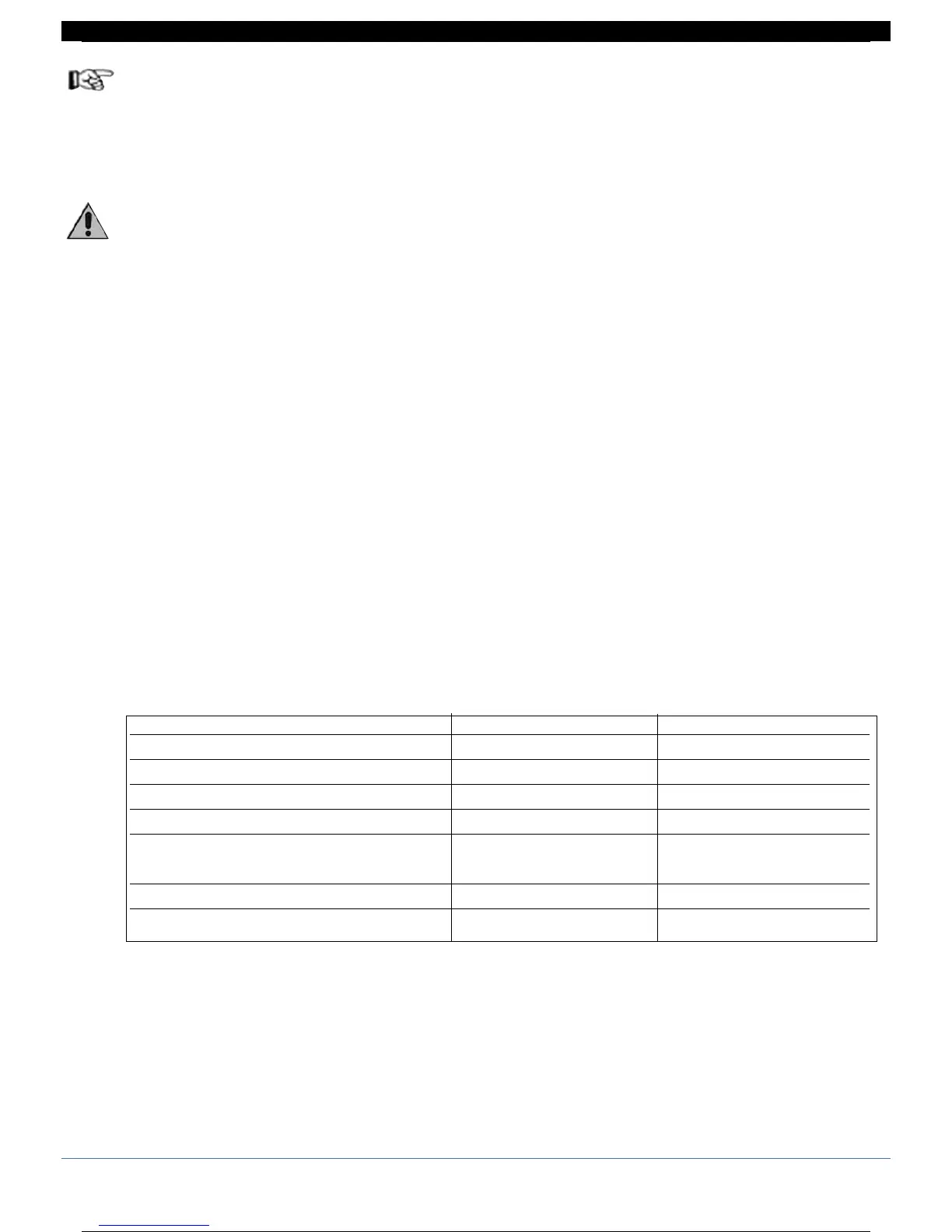
EMC conformity has been tested with the following con-
nections.
Function Cable type Length
Power supply cable 1mm
2
1m
Relay output cables 1mm
2
3,5m
Serial connection wire 0,35mm
2
3,5m
Thermocouple input 0,8mm
2
compensated 5m
Strain gauge input, potentiometers, linears,
“PT100” temperature resistance 1mm
2
3m
Control and retransmission analog outputs 1mm
2
3,5m
Digital Inputs / Outputs 1mm
2
3,5m
4 80291G_MHW_2500_08-2010_ENG
4 / 77

 Loading...


