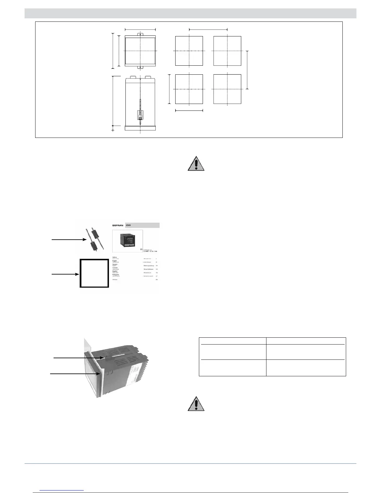
Dimensions and cut-out
96
115
108
96
10
92
92
115
170
Installation with panel mounting
As well as the actual controller and these instructions for
use, the controller package also contains:
•n°2panelfixingbrackets(A)
•n°1protectivesealagainstdustandwaterspray(B)
Fit the controller to the panel as shown in the figure.
Warnings and instructions for mounting to the panel
Instructions for installation category II, pollution
level 2, double isolation.
• Theequipmentisintendedforpermanentindoorinstalla-
tions within their own enclosure or panel mounted
enclosing the rear housing and exposed terminals on
the back.
• only for models with 20...27Vac/dc power supply: supply
from Class 2 or low voltage limited energy source
• thepowersupplylinesmustbeseparatefromthe
controller input and output ones
• grouptheinstrumentstogetherkeepingthemseparate
from the powered part of the relay
• donotinstallhigh-powerremoteswitches,contactors,
relays, thyristor power units (especially the “phase angle”
type), motors, etc. in the same switchboard
• avoiddust,humidity,corrosivegassesandheatsources
• donotblocktheventilationholes:theworkingtempera-
ture must be between 0...50°C
• surroundingair:50°C
• use60/75°Ccopper(Cu)conductoronly,wiresizerange
2x N. 22 - 14AWG, Solid/Stranded
• useterminaltighteningtorque0.5Nm
Nominal ambient conditions
Before supplying the Controller with power,
make sure that the mains voltage is the same as
that shown in the last number of the order code.
Example:
2500 – x – x – x – x – x – 1 = 100..240Vac/dc
2500 – x – x – x – x – x – 0 = 20..27Vac/dc
A
B
A
B
Altitude Up to 2000m
Working/storage 0..50°C/-20...70°C
temperature
Non condensing 20...85%
relative humidity
6 80291G_MHW_2500_08-2010_ENG
6 / 77

 Loading...


