6 • MAINTENANCE
This section gives the information and the necessary
warnings for routine maintenance of the 2500 control-
lers and contains a Troubleshooting Guide which should
be read before seeking help from the Gefran Customer Service
Assistance, in the event of instrument malfunction.
If installed and configured correctly according to the
instructions and the recommendations provided in Sections 2
and 4 of these Instructions for use, the 2500 Controller will work
normally without any need for maintenance, apart from the usual
operations of cleaning the faceplate, and if necessary the internal
parts of the instrument.
To gain access to the inside of the instrument (for
example for cleaning or to check the jumpers) just
undo the screw at the bottom of the faceplate and
take out the instrument without having to disconnect
the cables.
Make sure that the power is turned off upstream of
the instrument however.
Remember that the 2500 Controller is not equipped
with an ON/OFF switch.
Cleaning the Controller
To clean the faceplate and the case use only a cloth
dampened in water or ethyl alcohol.
Do not use hydrocarbon-based solvents (trichiorethylene,
petrol, etc.).
Do not use compressed air to remove dust from the
electronic circuit boards, if necessary use a clean brush
with soft bristles.
Repairs
Repairs to the Controller must only be carried out by
qualified technicians, properly trained and authorized by
Gefran.
Any attempts at repair or modification of the Controller
hardware characteristics by unauthorized personnel will
invalidate the warranty.
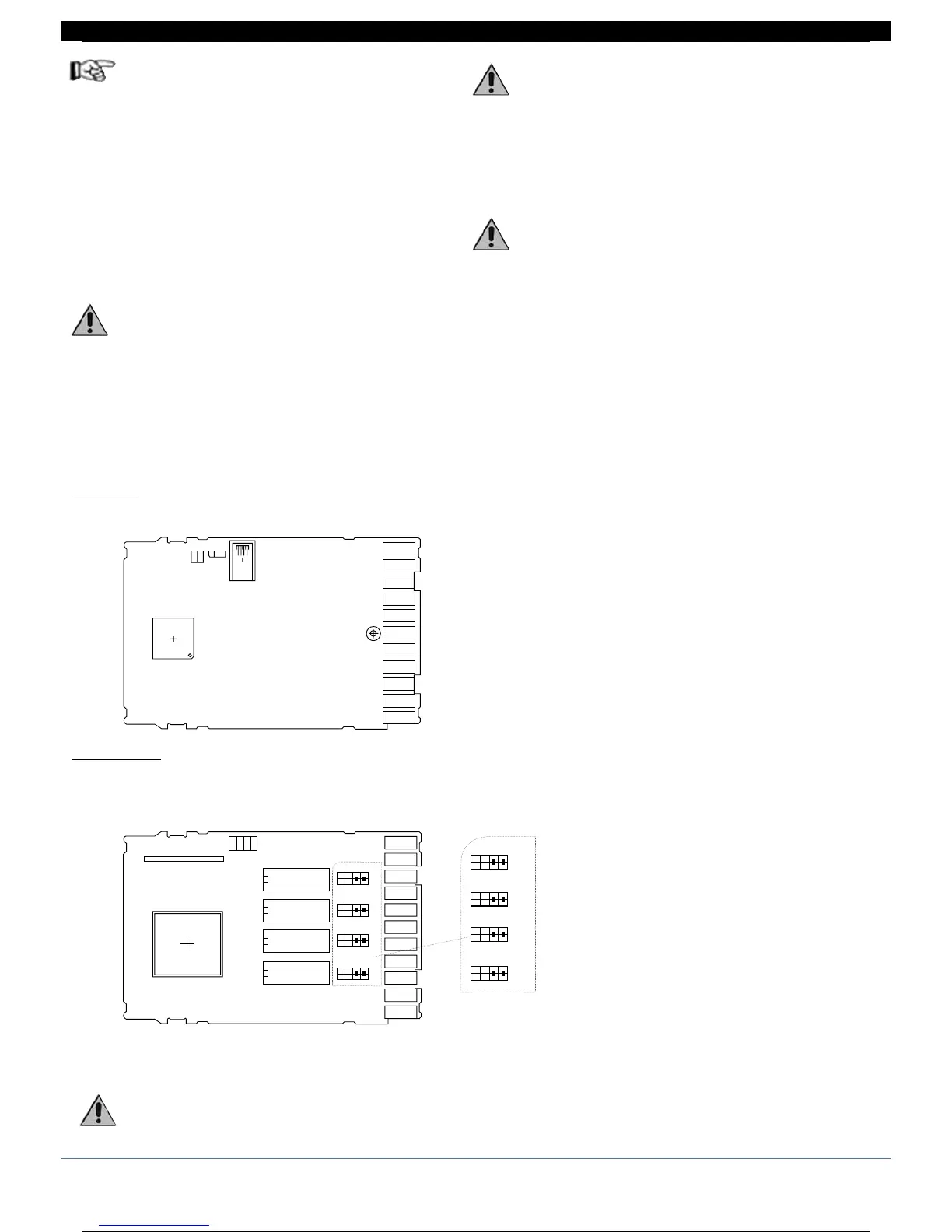
Checking the jumpers
CPU Board
The component side of the CPU board contains the jumper S9 which enables (if on) access to the controller menus.
J1A
J2A
J3A
J4A
J5A
J6A
J7A
J8A
J9A
J10A
J11A
J6
IC9
S9
S10
S8
1 2 3
CPU Board
POWER Board
Jumpers J1, J2, J3, J4 for selection of contact type no/nc for the relay outputs are present on the component side of the
POWER board, accessibility on welding side (LS).
Remove S1, ..., S4 jumpers to reverse OUT1, ..., OUT4 output status.
The controller contains components which are sensitive to electrostatic discharge, so the relevant precau-
tions must be taken when handling the electronic circuit boards contained in it, in order to avoid permanent
damage to components themselves.
nc4 no4
J4
J3
J2
J1
nc3 no3
nc2 no2
nc1 no1
J1, ..., J4 jumpers are made with double jumper; move both
jumpers in the requested position to change type of contact.
J5
T1
nc4 no4
J4
J3
J2
J1
J12
J13
J14
J15
J16
J17
J18
J19
J20
J21
J22
K4
K3
K2
K1
S4
S3
S2
S1
nc3 no3
nc2 no2
nc1 no1
POWER Board
56 80291G_MHW_2500_08-2010_ENG
56 / 77

 Loading...


