EXAMPLES OF CUSTOM LINEARIZATION
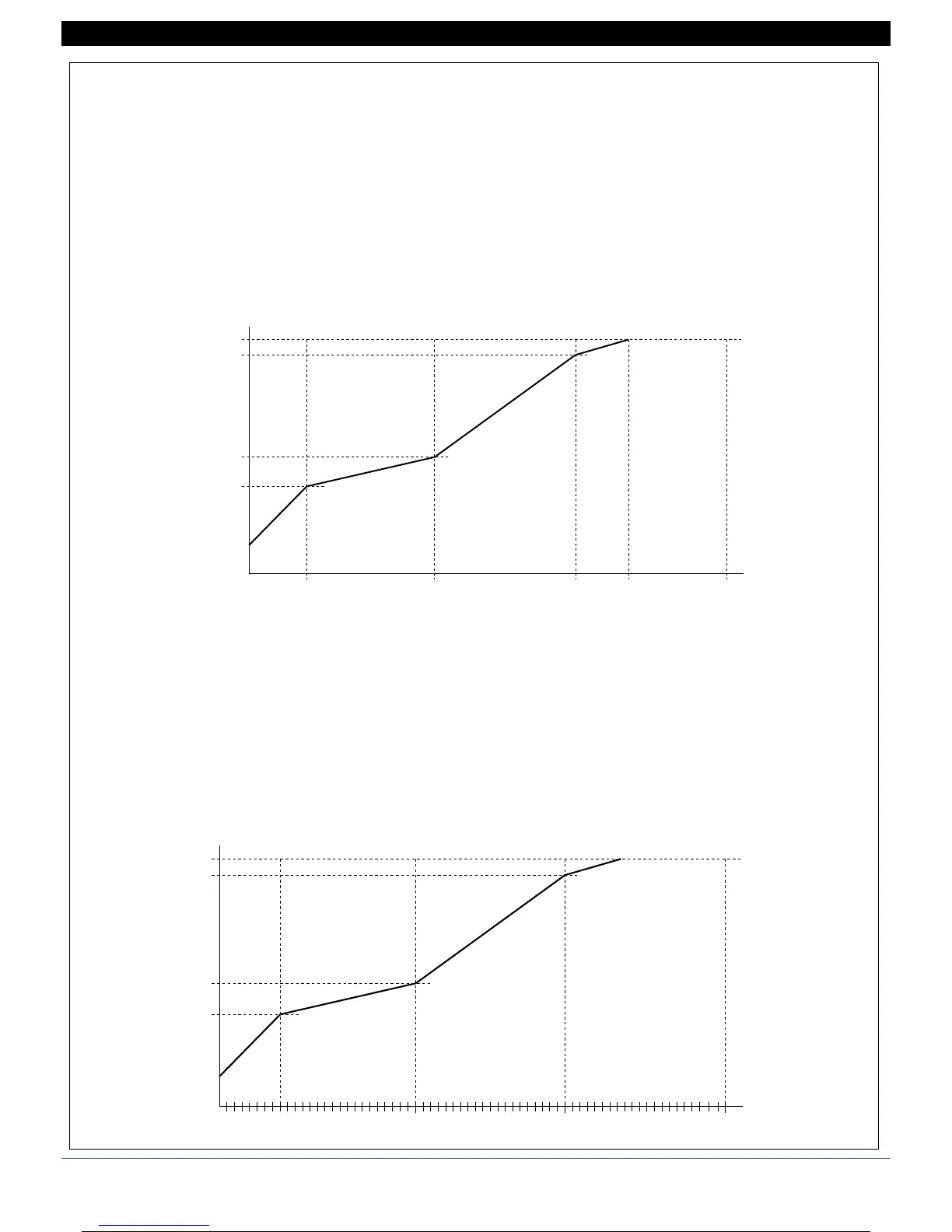
Example of custom linearization: type 0
(at variable amplitude intervals, max. 32)
For positive polarization signals (ex. 0...50mV) S.00 is the value displayed for minimum input (ex. 0mV);
if 32 intervals are set, S.32b is the value displayed for input = S.32A * (f.s. / 10000)
(ex. if S.32A = 10000, S.32b is the value displayed with input = 50mV)
For symmetrical polarization signals (ex. -25mV...+25mV) S.00 is the value displayed for minimum input (ex. -25mV);
if 32 intervals are set, S.32b is the value displayed for input = S.32A * (f.s. / 10000)
(ex. if S.32A = 10000, S.32b is the value displayed with input = +25mV)
In case of linearization type 1, ... ,4 S.nnA values are acquired directly by its input IN1, ... ,IN4
Example of custom linearization: type 5
(at 64 constant amplitude intervals = f.s. / 64)
For positive polarization signals (ex. 0...50mV) S.00 is the value displayed for minimum input (ex. 0mV);
S.64 is the value displayed for maximum input (es 50mV)
For positive polarization signals (ex. -25mV...+25mV) S.00 is the value displayed for minimum input (ex. -25mV);
S.64 is the value displayed for maximum input (ex. +25mV)
0
S.01A