VDL200 • Quick installation guide - Specifications and connection 13
4.4 Input electrical data
Choke ������������������������������� Sizes 1...2: Optional (DC or AC).
Note! See chapter 5.2 for THD values in accordance with EN 12015 and for selection of external inductances.
Size
Input
voltage
Uln
Input
frequency
Overvoltage
threshold
(Vdc)
Undervoltage
threshold
(Vdc)
Effective input current In (@ In out)
DC-Link
Capacity
(Vac) (Hz) @ 230 Vac (A) @ 400 Vac (A) (µF)
VDL200-...-4 , 3ph
1040
three-phase
230 - 400 Vac
-15%+10%
50/60 Hz,
± 5%
820 Vdc
@ 230 Vac = 225 Vdc;
@ 380 Vac = 371 Vdc;
@ 400 Vac = 391 Vdc.
12 11 470
1055 17 16 680
2075 23 22 680
2110 31 29 1020
3150 42 40 1500
3185 50 47 2250
3220 55 53 2700
4.5 Output electrical data
Maximum output voltage U2 �������������� 0.98 x Uln (Uln = AC input voltage)
Maximum output frequency f2 ������������� 300 Hz
The derating factors shown in the table below are applied to the rated DC output by the user. They are not automati-
cally implemented by the drive: Idrive = In x Kx K.
Size
I
n Rated output current
(fsw = default)
Pn mot
(Recommended motor power ,fsw
= default)
Reduction factor
IGBT
braking unit
@U
ln = 230Vac @Uln = 400Vac @Uln = 230Vac @Uln = 400Vac Kt Kalt
(A) (A)
(kW) (kW)
(1) (2)
VDL200-...-4, 3ph
1040 9 9 2 4 0.95 1.2
Standard internal
(with external
resistor); braking
torque 150% MAX
1055 13.5 13.5 3 5.5 0.95 1.2
2075 18.5 18.5 4 7.5 0.95 1.2
2110 24.5 24.5 5,5 11 0.95 1.2
3150 32 32 7.5 15 0.95 1.2
3185 39 39 9 18.5 0.95 1.2
3220 45 45 11 22 0.95 1.2
(1) K: Derating factor for ambient temperature of 50°C (1% every °C above 45°C)
(2) K: Derating factor for installation at altitudes above 1000 meters a.s.l. Value to be applied = 1.2% each 100 m increase above 1000 m.
E.g.: Altitude 2000 m, Kalt = 1.2% * 10 = 12% derating; In derated = (100 - 12) % = 88 % I
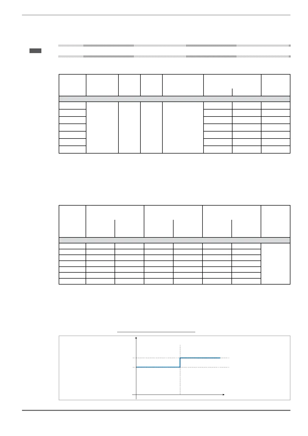
4.5.1 Derating values in overload condition
Figure 4.5.1-A: Ratio between overload/output frequency
150
200
F out (Hz)
OL (% I)
N
 Loading...


