36 VDL200 • Quick installation guide - Specifications and connection
8. Use of the keypad
This chapter describes the optional KB-ADL keypad and methods of use for displaying and programming inverter
parameters.
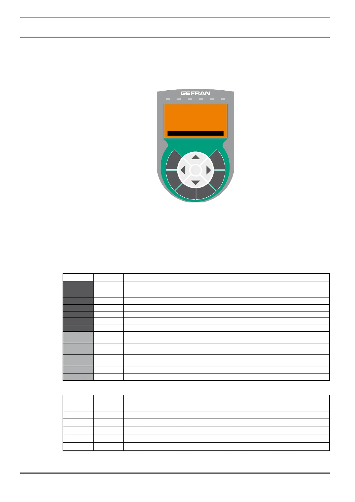
8.1 Description of KB-ADL optional programming keypad
Drive status indicator LEDs
BRK CNT EN ILim n=0 AL
E
DISPESC
SAVE CUST
FIND RST
01 MONITOR
02 DRIVE INFO
03 STARTUP WIZARD
04 DRIVE CONFIG
05 LIFT
5-line x 21 character alphanumerical LCD display
Membrane keypad
The optional programming keypad is used to display the status and diagnostics parameters during operation. It has
a strip of magnetic material on the back so that it can be attached to the front of the drive or other metal surface (e.g.
door of the electrical panel). The keypad can be used remotely from distances of up to 15 m. A 70 cm-long connection
cable is supplied as standard. Up to 5 sets of parameters can be saved using the KB-ADL keypad and sent to other
drives.
8.1.1 Membrane keypad
This section describes the keys on the membrane keypad and their functions
Symbol Reference Description
ESC Escape
Returns to the higher level menu or submenu. Exits a parameter, a list of parameters, the list of the last 10 parameters and the
FIND function.
Can be used to exit a message that requires use of this.
SAVE Save Saves the parameters directly in the non-volatile memory without having to use 4.1 Save parameters
FIND Find
Enables the function for accessing a parameter using its number. To exit these functions, press the
key.
RST Reset Resets alarms, only if the causes have been eliminated.
CUST Custom
Displays the last 10 parameters that have been modified. To exit these functions, press the
key.
DISP Display Displays a list of drive functioning parameters.
E Enter
Enters the submenu or selected parameter, or selects an operation. It is used when modifying parameters to confirm the new
value that has been set.
Up
Moves the selection up in a menu or list of parameters.
During modification of a parameter, increases the value of the digit under the cursor.
Down
Moves the selection down in a menu or list of parameters.
During modification of a parameter, decreases the value of the digit under the cursor.
Left Returns to the higher level menu. During modification of a parameter, moves the cursor to the left.
Right Accesses the submenu or parameter selected. During modification of a parameter, moves the cursor to the right.
8.1.2 Meaning of LEDs
LEDs Colour Meaning of LEDs
BRK Yellow The LED is lit when the drive has activated the brake release command
CNT Yellow The LED is lit when the drive has activated the close contactors command
EN Green The LED is lit during IGBT modulation (drive operating)
ILIM Red When this LED is lit the drive has reached a current limit condition. During normal functioning, this LED is off.
N=0 Yellow The LED is lit when motor speed is 0.
AL Red The LED is lit when the drive signals that an alarm has been triggered
 Loading...


