VDL200 • Quick installation guide - Specifications and connection 59
Appendix
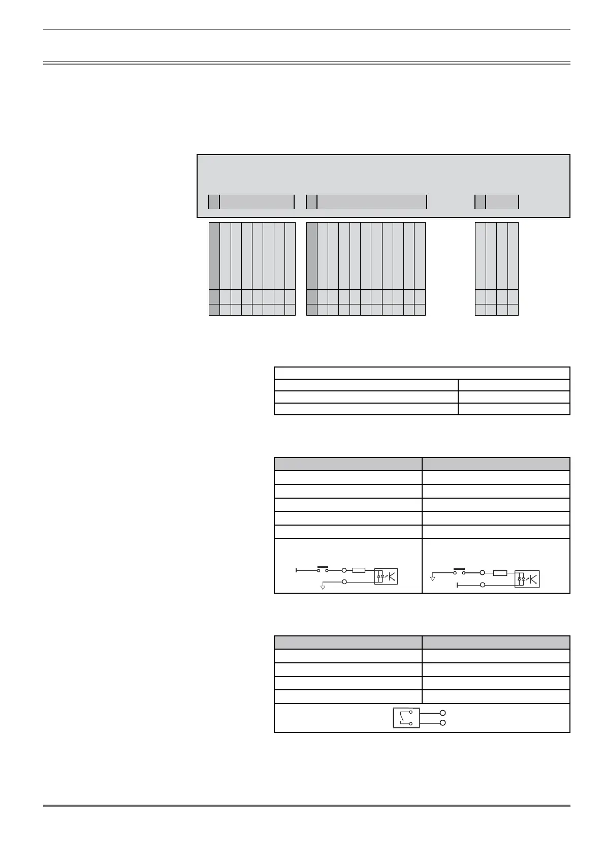
The I/O integrated in the R-VDL200 regulation card are: 1 enable input (Enable) + 8 digital inputs (DI) + 4 relay outputs
(RO) + 1 analog input (AI).
VDL200 (Asynchronous)
T3
T1
T2
Lift commands
Associated parameter
1416, Dig output 4X src
DoorOpen
1414, Dig output 3X src
Run Contactor
1412, Dig output 2X src
Brake Contactor
1410, Dig output 1X src
Drive OK
Contactor feedback
Feedback brake
Multispeed 2
Multispeed 1
Multispeed 0
Emergency
Start reverse
Start forward
RO
4O
RO
4C
RO
3O
RO
3C
RO
2O
RO
2C
RO
1O
RO
1C
DI
8
DI
7
DI
6
DI
5
DI
4
DI
3
DI
2
DI
1
EN
HW
DI
CM
OV
out
SH SH AI
-
AI
+
50 51 52 53 54 55 56 57 1 2 3 4 5 6 7 8 9 10 11 99 99 42 43
A.1.1 Input/Output features
24V DC power supply
Tolerance ± 10%
Maximum current 150 mA
Isolation 1 KV
Digital inputs (DI) and enable hardware inputs (EN-HW)
Description Features
Type 24 V PNP / NPN
Operating voltage 0 V to + 24 V (+ 30 V max)
Load 5 mA @ +24 V - R
l = 4.7 kΩ
Thresholds V
ic < 5 V – Vih > 15 V
Isolation Yes – Functional (> 1 kV)
PNP NPN
+24V
DI-CM
EN-HW
DI-X
4k7
EN-HW
DI-X
DI-CM
EN-HW
DI-X
4k7
EN-HW
DI-X
+24V
Relay outputs (RO)
Description Features
Type NO Relay (single contact)
Operating voltage 250 Vac / - 30 VDc / 2 A
Load 50 mA @ +10 V
Isolation Yes – 4 kV
 Loading...


