VDL200 • Quick installation guide - Specifications and connection 31
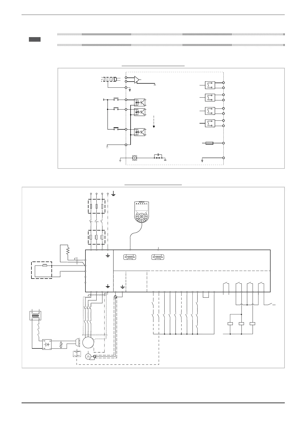
7.3 Connection diagrams
Note! This chapter describes the typical wiring diagrams with reference to VDL200 drives with standard configuration.
7.3.1 Regulation potentials, digital I/O
Figure 7.3.1.1: Regulation potentials (VDL200)
Chassis
+24V_OUT
0V (24V)_OUT
0V(+24V)
Isolated power supply
for Inputs/Outputs
HW Enable
Digital input 1
Digital input n
9
8
DI COM
Resettable fuse
n
+24V
12
11
10
57
Relay 1
Relay 2
56
Relay 3
Relay 4
55
54
53
52
51
50
Analog input 1
43
42
Shielded cable
99
Shield
7.3.2 Typical connection diagram
Figure 7.3.2.1: Typical connection diagram
AC
L1
1
2
K1M
3
4
5
6
F1
M
3
~
DC
L1
VDL200
U1
V1 W1
U2
V2
W2
RS232
DOOR
DI8
DI7
DI6
DI5
DI4
DI3
DI2
DI1
ENHW
DICM
0VOUT
24VOUT
L1 L2 L3
KEYPAD / DCP
PC
T1 T2 T3
123456789101112
PE
PE
50
51
D
C1
BR
EM
OPTIONAL
K2M
K3M
BrakeFbk
MltSpd S1
MltSpd S2
Emergency mode
MltSpd S0
StartFwdCmd
StartRevCmd
K2M
K3M
Safety
chain
OPTIONAL
BREAKING
RESISTORS
C
BRAKE
CONTACTOR
OK
DRIVE
52
53
54
55
CONTACTOR
RUN
56
57
L1
A1
A2
A1
A2
A1
A2
K2M
K3M BR
BRAKE
K2M
K3M
BR
TRAFO
3 Phase Mains
FBR
5
6
3
4
1
2
K2M
5
6
3
4
1
2
K3M
Emergency
Failure
(optional)
XE
PE