VDL200 • Quick installation guide - Specifications and connection 29
Figure 7.2.4: Recommended card wiring
7.2.3 Feedback Connection
This section describes the feedback connections for the asynchronous:
1) Connection digital encoder 3 Channels, TTL Line Driver / Push pull(DE)
2) Repeat Encoder (TTL line-driver)
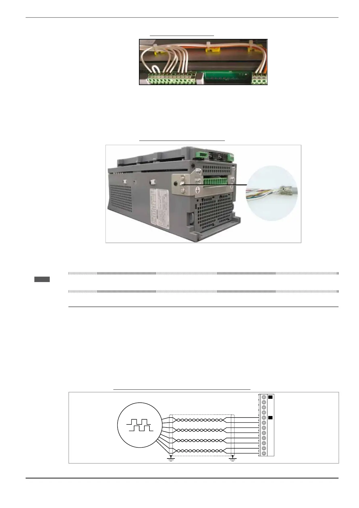
Figure 7.2.5: Connection of shielding (recommended)
1) Connection digital encoder 3 Channels, TTL Line Driver / Push pull (DE)
Note ! The encoder power supply must be adequate considering the cable length and the absorption rates as shown in paragraph "7.2.4 Internal power supply of the
encoder" .
(TTL Line-driver / Push pull)
Channels ������������������������������� A+ A-, B+ B-, Z+ Z-, differential line drivers, optoisolated.
Management of loss of encoder signals (via software).
Max frequency �������������������������� 100 kHz (check the number of encoder impulses according to the maximum speed)
Number of impulses ���������������������� min 128, max 16384 (default 1024)
Electrical interface ������������������������ TTL (ref. GND) Ulow ≤ 0.5 V Uhigh ≥ 2.5 V
Load capacity ��������������������������� 13 mA @ 5.5 V (Zin 300Ω)
Programmable internal power supply ���������� min +5.2 V, max +6.1 V (default + 5.2 V) − Imax 150 mA.
See paragraph "7.2.4 Internal power supply of the encoder" (step: 5.2V / 5.5V / 5.8V / 6.1V).
Cable length ���������������������������� max 50m
Digital Incremental Encoder: to
Figure 7.2.6: Connection Incremental digital encoder (DE), TTL Line Driver / Push pull
Z-
Z+
B-
B+
A-
A+
0VE out
+VE out
(*)
8
9
10
11
12
13
14
15
20
21
22
23
XE
XER
 Loading...


