30 VDL200 • Quick installation guide - Specifications and connection
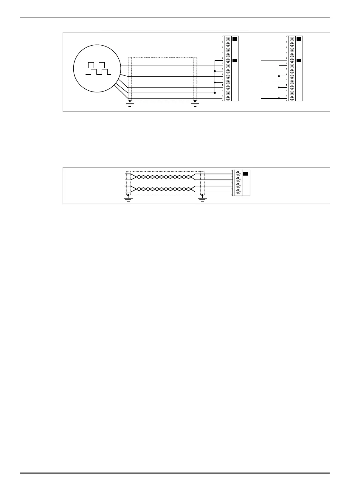
Figure 7.2.7: Connection Incremental digital encoder (DE), Single Ended PNP O.C./ NPN O.C
Z+
B+
A+
0VE out
+VE out
(*)
8
9
10
11
12
13
14
15
20
21
22
23
XE
XER
8
9
10
11
12
13
14
15
20
21
22
23
XE
XER
PNP NPN
Z-
B-
A-
0VE out
+VE out
Z-
B-
A-
Z+
B+
A+
2) Repeat Encoder (TTL line-driver)
Encoder expansion cards have an incremental encoder output with TTL/HTL Line Driver levels (according to the main
encoder supply) to be used to repeat the servomotor feedback device. This function is performed via HW and an
encoder output can be repeated with a programmable divider. The encoder output signals are available on the XER
connector:
B- out
B+ out
A- out
A+ out
(*)
20
21
22
23
XER
Channels ������������������������������� A+ A-, B+ B-, differential line drivers, optoisolated.
Max frequency �������������������������� 100 kHz
Number of impulses ���������������������� 1/1-1/2-1/4-1/8 repeat (default 1/1)
Electrical interface ������������������������ TTL (ref. GND) Ulow ≤ 0.5 V Uhigh ≥ 2.5 V
Load capacity ��������������������������� TTL 20mA @ 5,5V (Zin 120Ω) for each channel
Cable length ���������������������������� max 50m
7.2.4 Internal power supply of the encoder
The internal power supply of the encoder can be selected from the keypad (ENCODER CONFIG menu, parameter
Encoder supply (PAR 2102) to balance the loss of voltage due to the length of the encoder cable and load current.
PAR 2102 Encoder supply range: min=5.2V, max= 6.1V, step of 0.1V; default=5,2V.
/ 5.8V / 6.1V.
 Loading...


