32 VDL200 • Quick installation guide - Specifications and connection
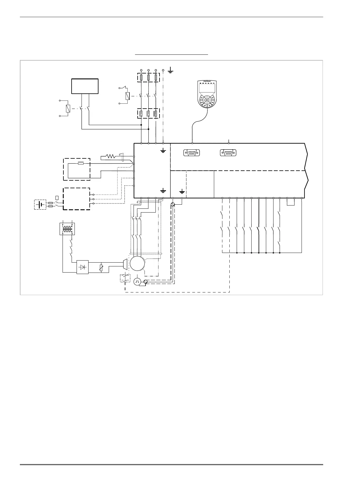
7.3.3 Emergency connection diagram
condition (with 230 VAC single-phase UPS power supply or EMS module).
Figure 7.3.3.1: Emergency connection diagram
AC
L1
1
2
S1
3
4
5
6
F1
VDL200
U1
V1 W1
U2
V2
W2
RS232
DI8
DI7
DI6
DI5
DI4
DI3
DI2
DI1
ENHW
DICM
0VOUT
24VOUT
L1 L2 L3
KEYPAD / DCP
PC
T1 T2 T3
12345678910 11 12
PE
PE
D
C1
BR
EM
3 PHASE MAINS
BrakeFbk
MltSpd S1
MltSpd S2
Emergency mode
MltSpd S0
StartFwdCmd
StartRevCmd
K2M
K3M
C
S2
US1
S2
US2
UPS
1ph, 230V
50Hz
DC
L1
EMERGENCY
MODE
SUPPLIER
OPTIONAL
BREAKING
RESISTORS
OPTIONAL
C
D
EM
DC CHOKE
Battery Pack
+
_
EMS (*)
KB
M
3
~
5
6
3
4
1
2
K2M
5
6
3
4
1
2
K3M
BRAKE
BR
FBK
-
+
~
~
K3M
K2M
Safety
chain
(optional)
XER
XE
PE
(*) EMS module instead of UPS device.
If an emergency power supply with UPS is used, the voltage on the DC_Link must not be below the minimum limit
of 230V. If this occurs, connect the EM terminal to an additional power supply (see above: emergency connection in
EMS mode).
 Loading...


