651
14/44
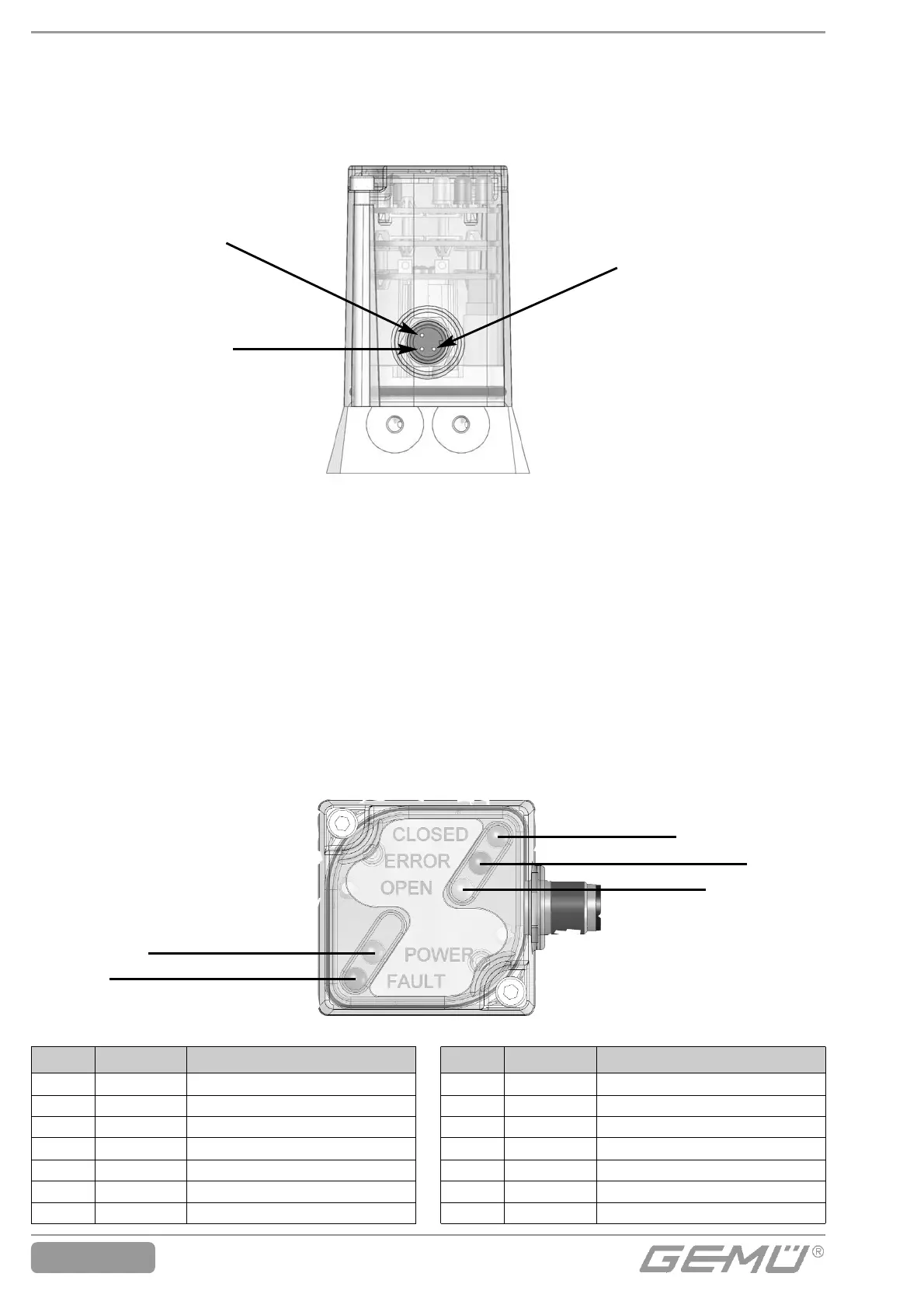
7.3 Optical indication
As well as the electrical position feedback
and error analysis (refer to the error table in
the technical data section), a visual signal is
emitted by LEDs that can be seen from above.
orange / orange
rot / red
gelb / yellow
7.3 Optische Anzeige
Zusätzlich zur elektrischen Stellungsrück-
meldung und Fehlerauswertung (Fehlerta-
belle siehe Technische Daten), erfolgt eine
optische Signalisierung mittels LEDs, die
von oben sichtbar sind.
grün / green
rot / red
LED Farbe Funktion
Fault
rot
Fehler
Power grün Power
Open
gelb
Prozessventil in AUF Stellung
Error rot Error
Closed orange Prozessventil in ZU Stellung
Y1
gelb
Pilotventil Y1 angesteuert
Y2 gelb Pilotventil Y2 angesteuert
LED Colour Function
Fault
red
Error
Power
green
Power
Open
yellow
Process valve in OPEN positon
Error
red
Error
Closed
orange
Process valve in CLOSED position
Y1
yellow
Pilot valve Y1 activated
Y2
yellow
Pilot valve Y2 activated
7 Connections and display
elements
7.1 Electrical connections
AS-Interface + (Pin 1)
AS-Interface + (Pin 1)
7 Anschlüsse und Anzeige-
elemente
7.1 Elektrische Anschlüsse
AS-Interface – (Pin 3)
AS-Interface – (Pin 3)
5-poliger M12
Anschlussstecker
für gelbe AS-Interface
Leitung (Anschluss
über GEMÜ 4180)
5 pin M12 plug for
yellow AS-Interface
cable (connection
via GEMÜ 4180)
7.2 Inputs and Outputs
Description of the inputs and outputs see
chapter 16 „Technical data automation
module.
7.2 Eingänge und Ausgänge
Beschreibung der Eingänge und Ausgänge
siehe Kapitel 16 „Technische Daten Auto-
mationsmodul“.
 Loading...