L
NAPCO Security Systems
X
GEM-P9600 Installation Instructions
WI742D 5/03
!
Page 15
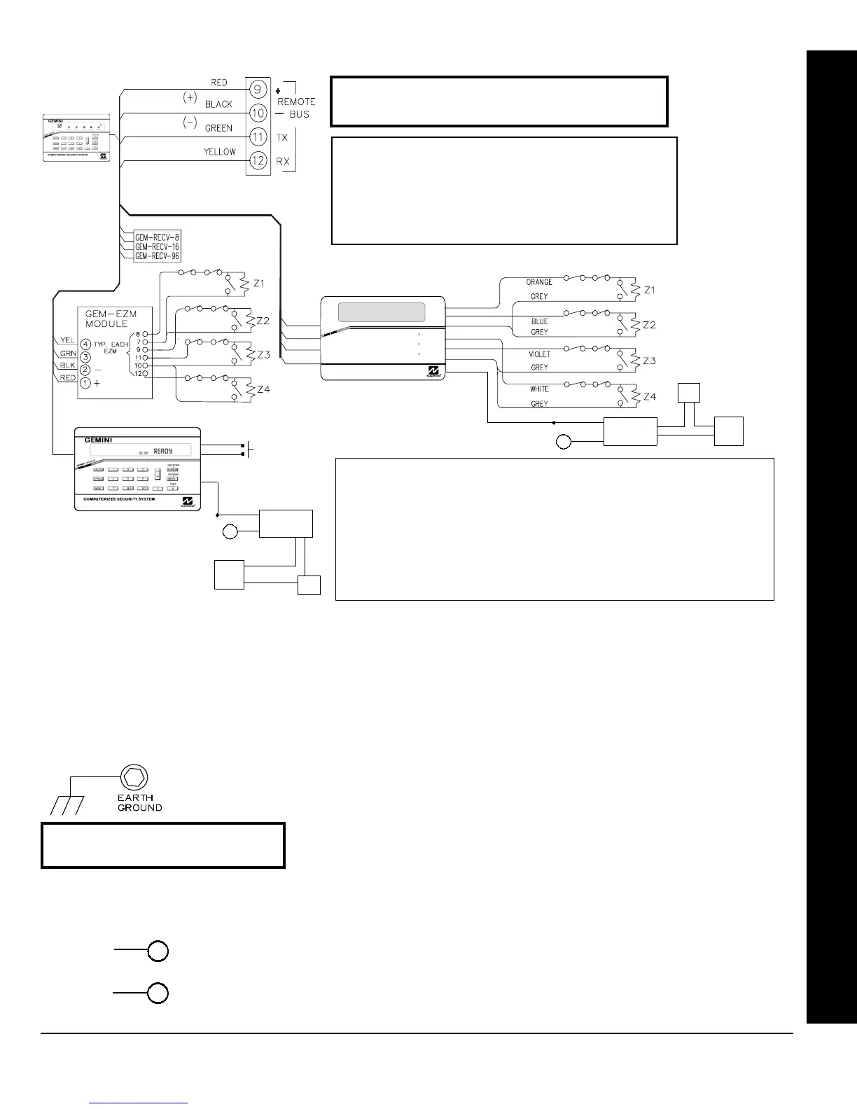
EARTH GROUND
NOTE: Do not use a gas pipe, plastic
pipe or AC ground connections.
Connect the control panel EARTH GROUND screw through a No. 16 AWG.
or larger wire to a metal cold-water pipe. Do not use a gas pipe, plastic pipe
or AC ground connections. Also, connect the circuit board to the metal enclo-
sure. Connect a wire with a ground lug crimped or soldered onto one end of
the EARTH GROUND screw to the cabinet.
NOTE:
Grounding connections
should avoid bends in the grounding wire whenever possible.
AUXILIARY POWER
Connect the auxiliary devices (motion detectors, glass breaks, etc.) to Terminals 13 and 14.
Auxiliary Power provides a filtered 12 VDC nominal output which is used for powering auxiliary
devices.
NOTE:
To calculate the available standby time refer to the Standby-Battery Calculation
Worksheet at the back of this manual.
13
(+)
14
(-)
AUX POWER
Connect the available devices as shown above to the remote bus terminals (9, 10, 11 & 12). Observe the correct color
wire connections. When connecting a keypads, first configure them accordingly (refer to the Keypad Configuration
Mode at the back of this manual). Keypads should be located near every exit/entry door. Up to 15 keypads may be
connected if the longest cable run from the panel, to the farthest keypad (daisy chained or home-run) is less than 1000
feet. The maximum distance for seven keypads is 300 feet using 22 AWG. wire. NOTE: When running keypad wire,
avoid wiring parallel to other types of wiring that can cause electrical interference.
WIRING CONNECTIONS
REMOTE BUS
Keypad Brown Wire: EZM/PGM Output Options
Select either option with GEM-RP1CAe2/GEM-K1CA keypads. Option 2 for use with GEM-RP2ASe2/
GEM-K2AS keypads only.
Option 1. Activates the PGM lug on the corresponding EZM module(s). Lug goes active (low) when
any selected Area is armed.
Option 2. The Access Code will activate the keypad's PGM brown wire while armed or disarmed if
the User Code is programmed for "Access Control on PGM Lug". The Access Code is pro-
grammed as any other User Code but without arm/disarm capability. Note: Options not investi-
gated by UL.
BROWN
BLK
RED
GEM-RP1CAe2
(2 LINE LCD KEYPAD)
(EZM/PGM Options 1 or 2)
R
COMPUTERIZED SECURITY SYSTEM
GEMINI
ARMED
STATUS
SYSTEM ARMED
01/01/97 12:00AM
12
4
3
56
7890
A
B
C
D
E
F
G
NEXT/YES
PRIOR/NO
AREA
GEM-RP3DGTL
AVAILABLE DEVICES
1.
KEYPADS:
GEM-RP1CAe2, GEM-RP2ASe2, GEM-RP3DGTL, GEM-
K1CA, GEM-K2AS and GEM-K3DGTL.
2.
X-10 INTERFACE:
GEM-X10
3.
WIRED ZONE EXPANDER:
GEM-EZM4 & GEM-EZM8
4.
WIRELESS RECEIVERS:
GEM-RECV8, GEM-RECV16 & GEM-RECV96
5.
RELAY MODULE:
RM3008
6.
VOICE INTERFACE:
GEM-EVA 1
7.
TELEPHONE INTERFACE:
WIZARD IIe
NOTE: Refer to the EZM Installation Instructions for
specific wiring information.
PANIC
GEM-RP2CAe2
(1 LINE LCD KEYPAD)
(Only PGM Option 2 available)
WHITE
WHITE
13
(+)
(–)
(N/O)
(COM)
BLK
RED
External
Power
Supply
Door
Strike
BROWN
BLK
RED
13
(+)
(–)
BLK (N/O)
(COM)
RED
External
Power
Supply
Door
Strike
RB1000 Relay
(recommended)
RB1000 Relay
(recommended)

 Loading...


