X
GEM-P9600 Installation Instructions
L
NAPCO Security Systems
WI742D 5/03
!
Page 30
KEYPAD MESSAGES
The GEM-RP1CAe2/GEM-K1CA Keypad can display the following messages. The GEM-RP2ASe2 and GEM-K2AS keypads will dis-
play similar abbreviated messages that may scroll through two screens.
SYSTEM READY CW1 - All zones operating; system can be
armed. GEM-RP1CAe2 only: C = Chime Mode on; W =
Watch Mode on; 1-8 = Area.
PLEASE WAIT - Panel reporting to central station on arming.
Wait for ringback signal to exit.
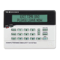
EXIT TIME XXX SI1 - Exit delay in progress. XXX = exit time
remaining in 10-second decrements; GEM-RP1CAe2 only:
S = Service Code active; I = arming with Instant protection;
1-8 = Area.
ENTRY TIME XXX - Entry delay in progress. XXX = entry time
remaining in 10-second decrements.
SYSTEM ARMED SI1 - Panel armed. GEM-RP1CAe2 only: S =
Service Code active; I = arming with Instant protection; 1-8
= Area.
CHECK STATUS CAW - One or more zones not secured. Dis-
play status for zone description(s). GEM-RP1CAe2 only: C
= Chime Mode on; W = Sensor Watch Mode on
CAN'T ARM/ZONES NOT NORMAL
- Arming attempted with
Priority Zone in trouble. Secure zone to arm.
DAY ZONE TRBL - Trouble condition on Day Zone, followed by
one or more zone descriptions.
INVALID ENTRY/TRY AGAIN - Wrong code/time/area number
entered.
CAN'T ARM SYSTEM - Arming attempted with System Trouble
present. Press the
C button and then arm the sys-
tem.
ALARM
- Alarm condition, followed by one or more zone de-
scriptions.
****FIRE**** - Fire alarm condition, followed by one or more zone
descriptions.
FIRE TROUBLE - Trouble condition on a Fire Zone. Press
C button to silence the sounder. Correct the trouble,
then press the C button again.
FIRE ALARM - Alarm condition on a Fire Zone. Press the
C button to silence the sounder. Correct the cause of
the alarm, then press the
C
button again.
ZONES BYPASSED - (When Zones Bypassed displayed) Indi-
cates zones that have been deactivated.
OV(R-) - Overview Mode (Status of up to 8 areas): R=Zone
Ready; also, Z=Zone Fault; A=Armed; B=Burglary Output;
F=Fire Alarm; T=Fire Trouble; C=Check Trouble; Display
Mode.
SYSTEM TROUBLE - A System Trouble display will be followed
by one or more of the following error codes:
E01-00 - AC POWER FAIL.
Power failure. Check power
transformer. Check for blown fuse or circuit breaker;
general power outage.
E02-00 - LOW BATTERY. Battery below 11 volts. If not
recharged within 24 hours, replace it.
E03-00 - COMM FAIL.
Unsuccessful communication to
central station. Note: Will also display if panel improp-
erly programmed to report; i.e., Report Alarm, Report
Codes, Subscriber ID Numbers, etc. must be pro-
grammed.
E04-NN - WL TRBL. Wireless transmitter supervisory fail-
ure. NN = transmitter number.
E05-NN - WL LOBATT. RF transmitter low battery. NN =
transmitter number.
E06-NN - RF REC TROUBLE.
RF receiver response trou-
ble. NN = receiver number.
E07-00 - DOWNLOAD FAIL. Download failure.
E08-00 - TELCO LINE1 FAIL. Telephone line failure
(system trouble displays after a programmed delay).
E09-00 - NOT PROGRAMMED. System cold start.
E10-NN - BURG KEYPAD TRBL.
Keypad response failure.
NN = keypad number.
E11-NN - BURG KPD TAMPER. Keypad cover removed.
NN = keypad number.
E12-NN - BURG EZM TRBL.
Expansion zone module fail-
ure. NN = module number.
E13-NN - BURG EZM TAMPER. EZM module cover re
moved. NN = module number.
E14-NN - RELAY BOARD TRBL. Relay board response
failure. NN = relay board number.
E15-NN - WL TAMPER. Transmitter cover removed. NN =
transmitter number.
E16-NN - RF REC JAMMED. Receiver jammed. NN = re-
ceiver number.
E17-NN - RF REC TAMPER. Receiver cover removed. NN
= receiver number.
E18-NN - LOBATT KEYFOB. Key fob transmitter low bat-
tery. NN = key fob transmitter number.
E19-00 - USER MEM ERROR.
Internal memory error. Se-
lect RESET SYSTEM TBL. Press the
J
button, then
the
C button.
E20-00 - DEALER MEM ERROR. Same as above.
E22-NN - PIR SENSOR TRBL.
No trip detected on PIR
Supervision Zone within programmed Sensor-Watch
time. NN = Zone number. To reset, press YES
(
E) button at “
RESET SENSOR MSG
” function display.
E23-00 - BURG BUS FAILED. Failure of 4-wire bus.
Check Terminals 11/12.
E24-00 - TIME FOR SERVICE. A service message can be
programmed through the PCD3000 Quickloader
(event-schedule screen) to remind the user to arrange
for scheduled maintenance. At the programmed date
and time, the keypad sounder will start to pulse and
the display will read “
TIME FOR SERVICE
” (GEM-RP1CAe2)
or “
SERV
” (GEM-RP2ASe2). This condition will behave
as a system trouble and may be cleared as such, i.e.,
press
C to silence sounder; access RESET
SYSTEM TRBL, then press the
J
button.
E27-00 - Printer Failure. Call installing company for service.
E39-00 - RF CAPACITY TRBL.
Receiver capacity error.
E51-00 - Alarm Output Supervisory.
E99-00 - Keypad panic shorted too long. GEM-RP2ASe2 /
GEM-RP3DGTL only.
NN OUT OF SYSTEM - Keypad inoperative. NN = keypad
number.
ALARM - (After panel is disarmed) displays zones violated.
FAULT FIND - Fault-find Mode activated.
LOCATE - Locate Mode activated.
KEYPAD MESSAGES

 Loading...