L
NAPCO Security Systems
X
GEM-P9600 Installation Instructions
WI742D 5/03
!
Page 17
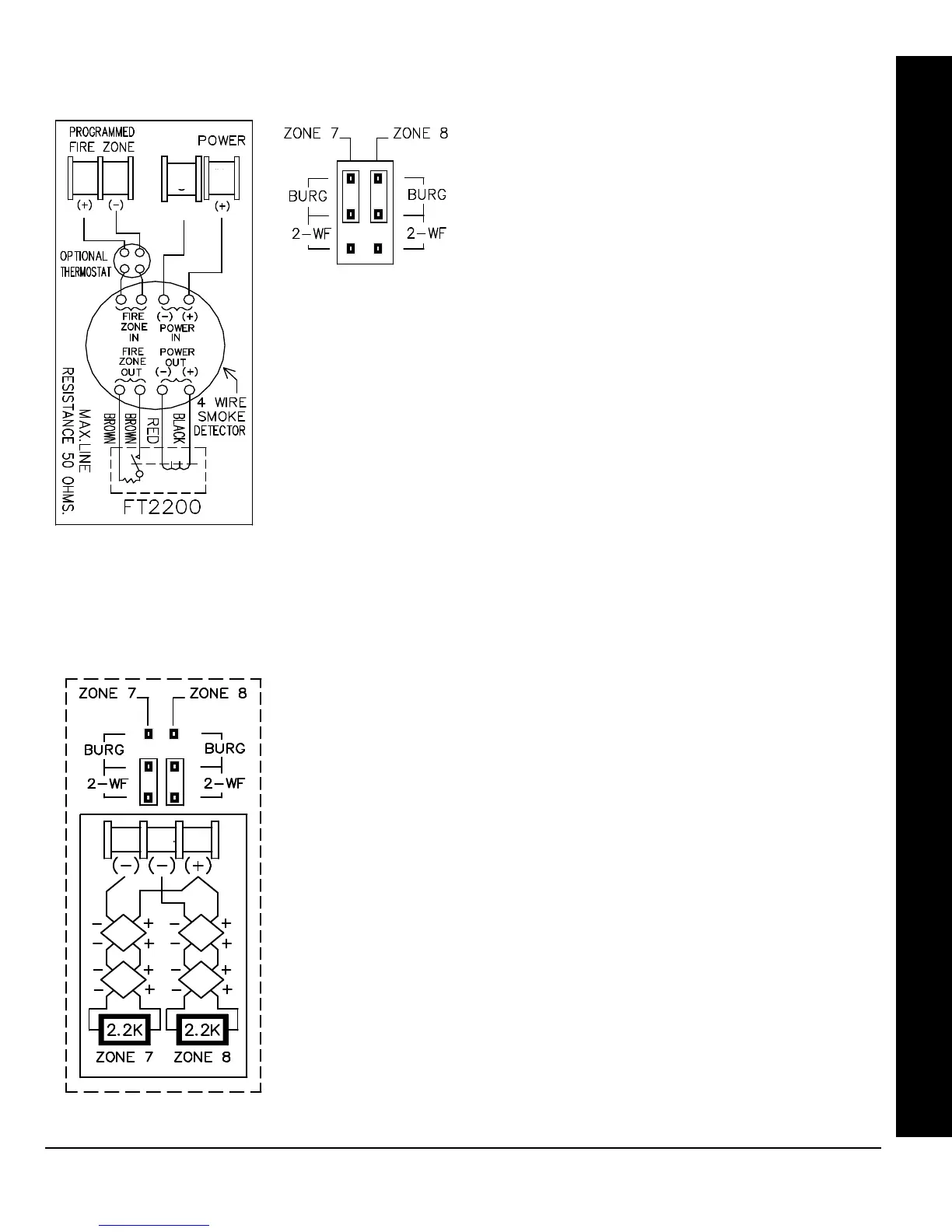
4-WIRE SMOKE DETECTORS
4-WIRE SMOKE DETECTOR WIRING
The GEM-P9600 can use conventional 12 VDC 4-wire smoke detectors. To use them,
the select fire zone programming option and do not select 2-wire smoke detector pro-
gramming option for the desired fire zone (refer to the GEM-P9600 Programming In-
structions). Set JP7 to the BURG position as shown, if zones 7 or 8 are to be used.
Four wire smoke detectors may be connected to any programmed fire zone (1-8) as
shown, within the panel. If external EZMs are used for zones 9-96, then 4-wire smoke
detectors may be connected to any programmed fire zones (9-96).
Power must be obtained from terminal 28 (+) and 29 (-). If Fire Alarm Verification is de-
sired to reset the smoke detectors, select this option for the desired fire zone.
NOTE: Do not program Fire Alarm Verification in California
Two-wire smoke detectors may be connected to control panel zones 1-8. Zones
7 and 8 may be configured for 2 wire fire through the JP7 jumper settings, while
zones 1-6 may be configured for 2 wire fire with the use of an EOL130 resistor
and the cut of a control panel resistor. To enable, program the zone(s) as Fire
Zones, enable 2-Wire Fire (refer to the GEM-P9600 Programming Instructions)
and set JP7 to the position as shown. Connect the 2-wire smoke detectors as
shown.
If Fire Alarm Verification is desired to reset the smoke detectors, select this op-
tion for the desired fire zone (zone 7 or 8).0
NOTE: Do not program Fire Alarm Verification in California
2-WIRE SMOKE DETECTORS
6
(-)
29
28
WIRING CONNECTIONS
2-WIRE SMOKE
DETECTOR WIRING
26 27 28

 Loading...


