ORTHORALIX 9200 Service Manual
A-5
Gendex Dental Systems 4519-190-71193-7
A.3 System identification
For system identification please refer to the technical label at A-14.
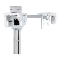
A.4 System components
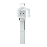
A.4.1 Column
The column is fixed to the wall with four bolts at the top and two
at the bottom.
It includes the counterweights required to balance the Z-carriage.
the Z-carriage is suspended by two steel cables with a balance
mechanism, ensuring a security lock in case one of the steel
cables breaks.
A sliding block on the front, to which the Z-carriage is bolted,
moves vertically along the column.
On the front of the column is the mains power box, to which the
mains power cable is connected.
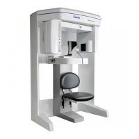
A.4.2 Z-Carriage
The Z-carriage slides along the column to adjust to the height
of the patient.
Movement is motorized driven manually by push buttons on the
operator panel.
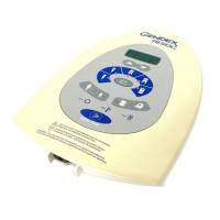
On the right there is the operator control panel, consisting of
a flat membrane keyboard with alphanumerical display and
indicator LEDs.
The internal mounting frame houses an electronic board that
controls the operator interface and the various motor movements.
The kinematic assembly allows for composite movements on the
X/Y plane by independent displacement of the X,Y blocks along
bearings, controlled by gear motors.
Another gear motor is located on the top frame, controlling the
rotational movement of the rotating unit.
A handgrip, bite block (or chin rest), and optical centering devices
provided on the Z-carriage help to position the patient during
exposures.
The bite block and chin rest are exchangeable.
On the right there is an attachment for mounting the Ceph arm.
A.4.3 Rotating unit
The rotating unit is suspended from the Z-carriage.
It carries:
a) the tubehead
b) the cassette drive system with the relevant gear motor
c) the panoramic digital sensor (DDE versions only).
The tubehead is connected by a flange, which can be manually
rotated for changeover from Pan mode to Ceph mode (not ap-
plicable for the DDE versions).
The power converter board, which supplies the high voltage and
filament supply for the tubehead, is located on top of the rotating
unit, on the tubehead side.
A.4.4 Tubehead
The tubehead contains the high voltage transformer and the
filament
transformer with the X-ray tube.
Thanks to the high frequency operation the tubehead features
are reduced in weight and size.
On the X-ray output window the X-ray collimator is mounted ; it
is slit type for Pan, TMJ and transversal scannographic exposures
and can be manually switched to a full size opening in case of
Ceph exposures.
A.4.5 Patient head rest
The patient head rest is attached to the Z-carriage.
It is motorized and controlled by a pair of pushbuttons on the
front operator panel.
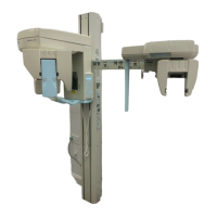
A.4.6 Ceph arm
The Ceph arm is bolted to the right side of the Z-carriage, and
comprises the cephalostat with cassette support.
In the DDE versions it includes:
a) the cephalostat
b) the ceph CCD digital sensor
c) the secondary collimator
e) the gear motor and related drive system to move the ceph
CCD digital sensor and the secondary collimator.
(03.0)E
 Loading...