3-3
OPERATING PROCEDUREUSER HANDBOOK
3.3 BATTERY STATUS
This feature provides the user
with a battery capacity level
indicator that displays instrument
battery power remaining, as
shown in Fig. 3.3.
This battery symbol will be
indicated for approximately ve
(5) seconds during the warm-
up cycle, then on the top of the
display during normal operation.
3.4 FILTER CHECK / FLOW FAULT TEST
Checking lters are in place and in good condition and performing a
regular leak check are pertinent to effective use of the GT instrument,
therefore, the user will be asked to conrm these checks before the
instrument completes the warm-up sequence. By default, these
checks should be performed on a daily basis.
Fig. 3.3 Battery Capacity
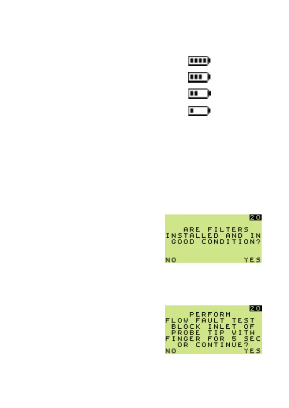
Fig. 3.4 Filter Check
3.4.1 Filter Check
If filters are installed, and in
good condition, press ‘YES’ for
instrument warm-up to continue.
If ‘NO’ is selected, instrument
will automatically enter ‘switch
off’ sequence.
Fig. 3.5 Flow Fault Test
3.4.2 Flow Fault Test
To perform a ow fault test, block probe tip inlet with nger for
approximately 5 seconds. Pump should ow fault and display screen
illustrated in Fig. 3.6.
If ‘YES’ is selected, instrument
warm-up will continue without
performing test.
If ‘NO’ is selected, instrument
will automatically enter ‘switch
off’ sequence.
 Loading...