4-2
LEAK TEST MODEUSER HANDBOOK
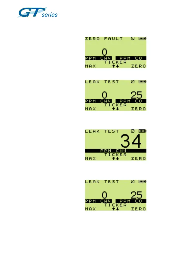
4.3 LEAK TEST DISPLAYS
During the warm-up period,
all applicable sensors will be
checked and the display will
indicate any sensor faults.
A positive zero fault is indicated
by a flashing gas reading, as
illustrated in Fig. 4.1.
A negative zero fault is indicated
by a spanner alternating with
a zero reading (not illustrated).
After the sensors have been
checked, the normal display will
be as shown in Fig. 4.2.
Note 1: Any faulty sensor will
continue to display a spanner
(wrench) symbol alternating with
the gas reading and the fault LED
will illuminate.
Note 2: Continuous display of
both flammable and CO is a
congurable option, as shown
in Fig. 4.3.
Fig. 4.3 Flammable / CO
Display
Fig. 4.2 Normal Display
Example
alternating with
Fig. 4.1 Sensor Check
 Loading...