5-2
CONFINED SPACE MODEUSER HANDBOOK
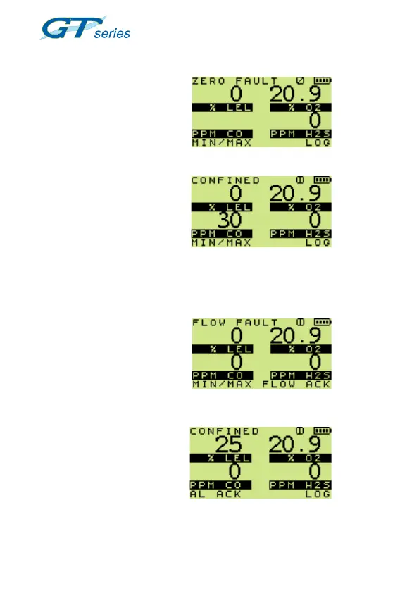
5.3 CSM DISPLAYS
During the warm-up period,
all applicable sensors will be
checked and the display will
indicate any sensor faults.
A positive zero fault is indicated
by a flashing gas reading, as
illustrated in Fig. 5.1.
A negative zero fault is indicated
by a spanner alternating with
a zero reading (not illustrated).
When an instrument has an
alarm active, the bottom line of
the display changes. A sample
fault will change both top and
bottom lines, as shown in
Fig. 5.2:
alternating with
5.1 Four Gas Sensor Check
alternating with
Fig. 5.2 Four-gas Display with
Alarm and Sample Fault
 Loading...