GMV5 Home DC Inverter Multi VRF Units
182
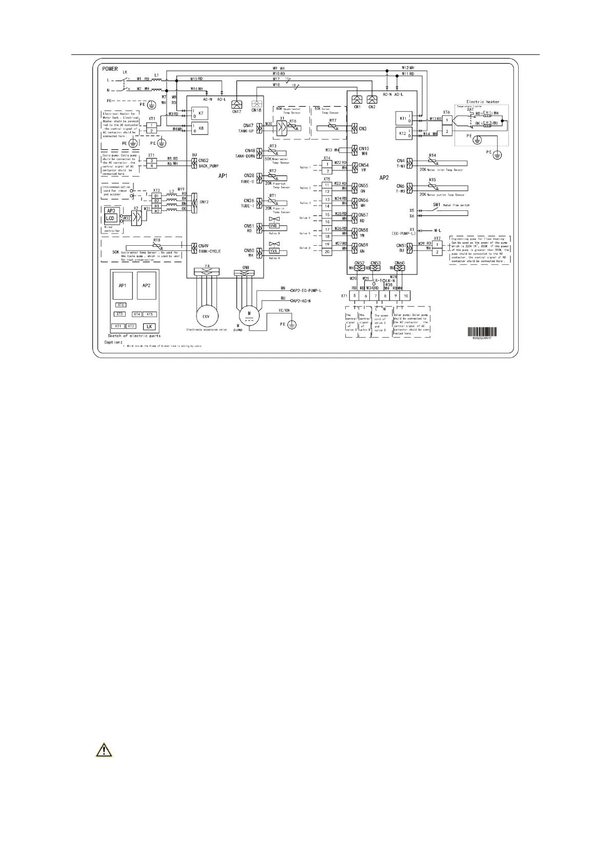
Note: The above wiring diagram is only for reference. Detailed content please refer to the
wiring diagram stuck in the electric box of unit.
12.3.3 Wiring diagram of IDU
Please refer to the related manual of IDU.
12.Installation of the Communication
System
The CAN communication network is adopted for GMV5 Home. Manual DIP or identification on
polarities of the communication cable is not required for the IDU. Only the function DIP needs to
be set for the ODU. For details, see the description on function setting of the ODU.
12.1 Connection of Communication Cable
12.1.1 Communication connection includes the following parts:
(1) Communication between ODU and indoor units (hydro box, IDUs).
(2) Communication between indoor units(hydro box, IDUs) and indoor units(hydro box, IDUs).
(3) Communication between IDU and wired controller.
(4) Communication between IDU and light board.
(5) Communication between hydro box and wired controller.
12.1.2 Communication way
GMV5 Home adopts CAN bus communication way.
12.1.3 Selection of the material of communication cable
Note:
For air conditioning units installed in places with strong electromagnetic interference, shielded
wire must be used as the communication cables of the indoor units and wired controller, and
shielded twisted pairs must be used as the communication cables between indoor units and
 Loading...