Page 11 of 87
The connection from the printer to the HC5500 is done through COM 1 or COM 2. The
printer is powered through the COM port so there is only one plug for the connection.
The configuration of the com port is done in Extended Menu 4.
In menu E4.1.1 Equipment type, Printer must be chosen and in menu E4.1.2 the baud rate
must be set to 9600.
In the section "Configuration of HC5500 to dump data” is a detailed description of the setup.
If the printer does not work, then check the connection to the COM port and see if it is
correct.
If it does not print, check the paper is threaded correctly (not reverse side).
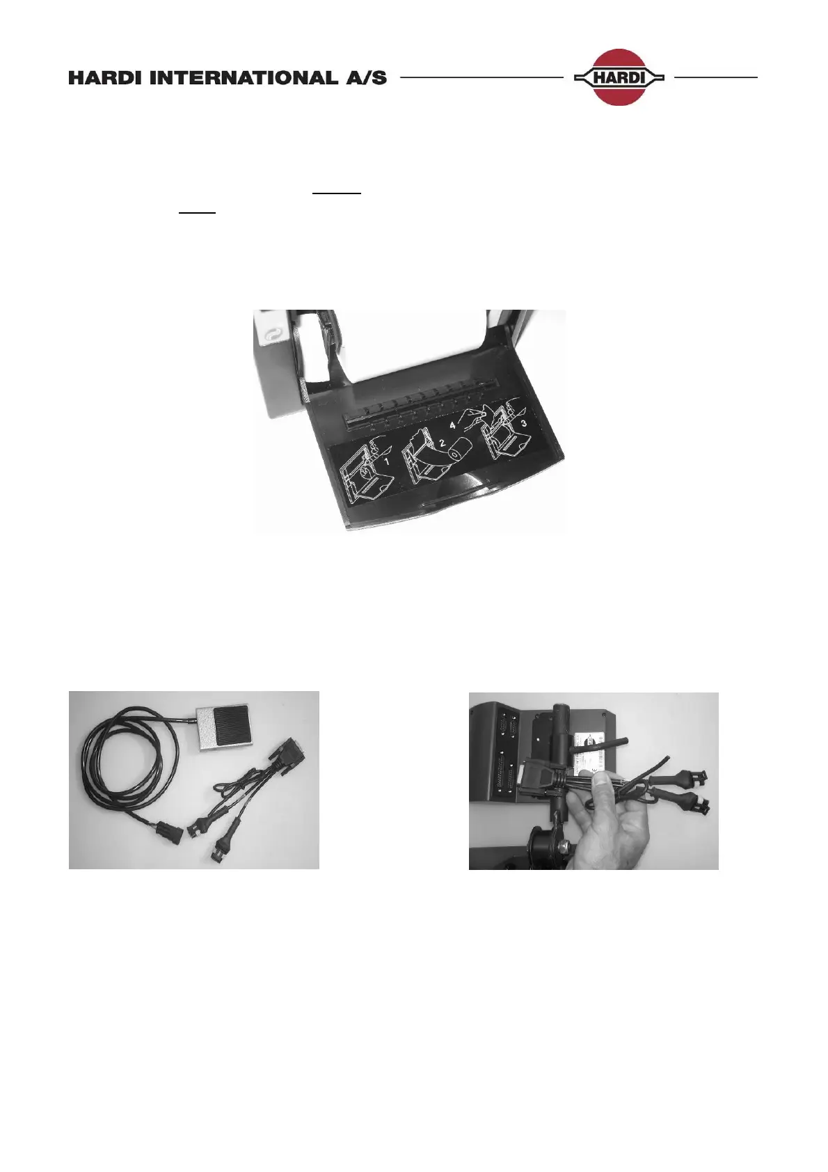
Foot pedal for main ON/OFF function
The foot pedal is an extra option for the HC5500. The pedal is connected through the wire
harness that can be seen on Picture 4 and Picture 5.
The wire harness is plugged into the AUX connector.
The “Speed2” connector has GND on pin1, +12V on pin 2 and Speed signal on pin 3.
The “Switch” connector has GND on pin 1, +12V on pin 2 and Switch signal on pin 3.
Picture 4: Foot pedal for the HC5500 Picture 5: Wire harness for the HC5500
The setup of the foot pedal to the HC5500 is done in E8.5.1. The menu tree can be seen in
section “Extended Menu 8”. There are two choices depending on the switch type.
The HC5500 can be set to a toggle or a pulse function. The standard HARDI foot pedal is a
toggle type.
 Loading...