Page 14 of 87
The version of the PCB used depends of what type of sprayer the sensor in mounted on.
For the wire connections to the PCB, see section “PCB’s” on pages 70.
When the pressure sensor is mounted on the sprayer, the HC5500 is setup to the sensor. In
menu “5” on pages 21, the setup is shown.
The pressure sensor has a fixed measuring range in Bar or PSI.
In Menu E5.1.1 the minimum value is typed in and in menu E5.1.2 the maximum is typed in.
The measuring range is written on the pressure transducer. Our standard is 0 to 10 Bar.
Note that the sensor is ignored if the minimum input is less than 3 mAmp.
In menu E8.1.3 is the minimum allowed pressure typed in. In practice, this means the
regulation will stop if the pressure goes below this value.
These setting are done in the Extended Menu.
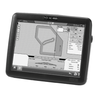
For a readout, the sensor must be setup. In Menu 2.1 Display readout / Optional sensor
Menu 2.1.3, the pressure sensor is chosen so the actual pressure can be seen.
Fan speed on TWIN
The Fan speed sensor can measure the revolutions on the blower unit on a TWIN sprayer.
The sensor is mounted on blower as shown in Picture 6.
For connecting the wiring from the Fan speed sensor see section “PCB’s” on pages 70.
Picture 6 Fan speed sensor
When the Fan speed sensor is mounted and the wires are connected, the HC5500 must be
setup for the sensor. In menu E5.2 the PPU value is set. The PPU value can be seen in the
menu E5.2.1. The default value is 1.
For a reading on the HC5500 display, the Fan speed sensor must be setup for the display.
In Menu 2.1, Display readout / Optional sensor, Menu 2.1.3, is the Fan speed sensor
chosen so the fan r/min can be seen.
Note the following for the Linak actuators on the TWIN FORCE sprayers
Spray II box &
Linak actuator
AMP
connector
Linak
Part no.
Voltage
(min to max stroke)
Signal
Breakout PCB 4 pin 262034 1.0 to 5.0 V Analogue
JobCom PCB 4 pin 262034 1.0 to 12.0 V PWM (Hz)
 Loading...