Page 12 of 87
Sensors:
Angle sensor Sensor AMP Con PCB
Blue Signal Signal 3 Signal
Black GND GND 1 -
Brown +12V +12V 2 +
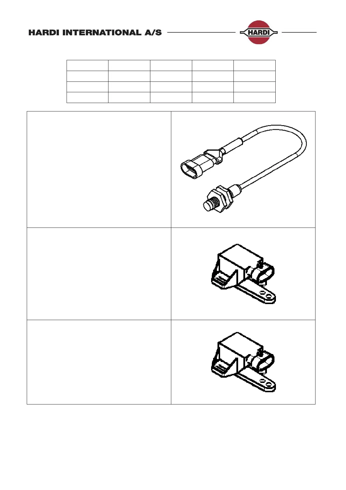
Speed, TWIN, Boom and SafeTrack lock
sensor
Hardi P/N 28047500
Type: Inductive
Range: 0-8mm
Signal: 0-200Hz
Operation indicator: Yellow light when
active (0,8V)
Power: 12V
Visual indicator: LED to indicate active
status
Hardi Pin assignment: Brown +
Blue signal
Black -
Front angle sensor:
Hardi P/N 26005700
Type: Potentiometer
Range: 0-70°
Signal: 0,5 - 4,5V
Centre position: 2,5 V
Power: 12V
Hardi Pin assignment: Brown +
Blue signal
Black -
SafeTrack rear sensor:
Hardi P/N 26005800
Type: Potentiometer
Range: 0-120°
Signal: 0,5 - 4,5V
Centre position: 2,5 V
Power: 12V
Hardi Pin assignment: Brown +
Blue signal
Black -
 Loading...