USE ONLY HAYWARD GENUINE REPLACEMENT PARTS
HRSLCSSPLMNTIOM Rev A
Page 11 of 42
Hayward Flow Control
1-888-HAY-INDL (1-888-429-4635)
www.haywardowcontrol.com
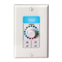
This round NEMA 4X/IP67 enclosure houses four pushbutton control switches that provide the
user with the ability to operate the actuator in a normal (REMOTE) mode where the actuator
responds to control signals from a building automation system or a PLC or other control device
(by others). Or the user can elect to operate the actuator in LOCAL mode where one can
control the positioning of the actuator while standing AT the device. This allows opening and
closing the actuator (valve) to test for operation, perform maintenance or other function without
relying on radio communication to command the automation system to position the actuator.
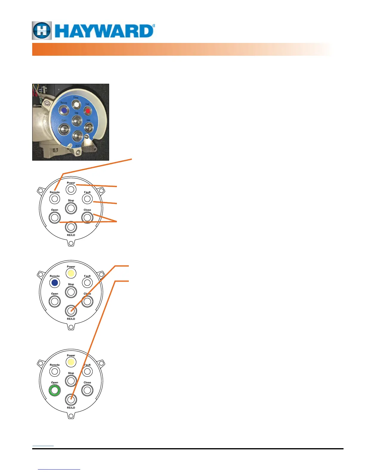
The panel houses three status LED’s that indicate Power, Remote operation, and a Fault
indicator. There are also four push button switches (non-latching, push/push) two of which
also have ring surround LEDs providing the operational status of the actuator. Whenever power
is present at the unit, regardless of MODE position, the Power LED is illuminated.
REMOTE (REMOTE MODE indicator, all actuators):
• The RE/LO mode switches from Local to Remote and back with each
successive press of the push button (see below).
• When the unit is in Remote mode, the Blue Remote LED will be illuminated.
• When the unit is in Local mode, the Remote LED will be OFF.
POWER (POWER indicator, all actuators): The Power LED is illuminated whenever power is
present at the unit, regardless of MODE position.
FAULT (FAULT indicator, all actuators): The Fault LED is illuminated whenever there is a fault
detected in the actuator.
OPEN/CLOSE (OPEN and CLOSE indicators, all actuators): Regardless of the Mode of
operation (other than powered OFF), the Open and Close push buttons have internal LED
rings which ash Red (Closing) or Green (Opening). When end of travel is reached, the LED
indicators remain constant ON.
RE/LO (REMOTE/LOCAL, all actuators): When the RE/LO push button is pressed, the mode
switches from Local to Remote and back with each successive press of the push button.
• REMOTE: When the unit is in Remote mode, the three Move push
buttons are disabled and have no effect on the operation of the actuator.
• LOCAL: When the unit is in Local mode (Blue LED OFF), the three Move
push buttons are enabled and one can control the position of the actuator
using the push buttons.
OPEN: Pressing the Open push button drives the actuator CCW until it reaches the end of
travel determined by the internal CCW travel cam settings.When pressed (momentary switch),
the unit will start and continue to drive until it reaches its full CCW position UNLESS the Stop
push button is pressed. This will arrest the CCW travel of the actuator and it will stay in its
current position UNLESS the manual handwheel is utilized.
CLOSE: Pressing the Close push button drives the actuator CW until it reaches its CW end of
travel limit switch.
STOP: Pressing the Stop push button stops the actuator in position.
Using the manual handwheel. In Remote mode with an active control signal present,
repositioning the actuator with the handwheel will result in the unit driving to maintain the
control signal command. i.e. if in Remote mode with a drive CW active control signal, if the
handwheel is utilized to reposition the actuator to mid-stroke, the motor will immediately drive
the actuator to its full CW position. While in Local Mode, the manual handwheel can be used
to reposition the actuator to any desired position AFTER the unit has reached its intended end
of travel position and the associated ring LED is illuminated.
This Control system employs a pad-lockable security plate that can be positioned over the
MODE push button and locked in place. This prevents changing the mode of operation. The lock
plate must be unlocked and swung out of the way to gain access to the mode switch function.
Operating the
Local Control Station
Panel shown with NO POWER
Panel shown in the
Remote Mode
Panel shown in the
Local Mode, actuator fully OPEN
ROUND LCS, PUSHBUTTON
CP SERIES LCS OPERATION
Back to TOC
 Loading...