USE ONLY HAYWARD GENUINE REPLACEMENT PARTS
HRSLCSSPLMNTIOM Rev A
Page 12 of 42
Hayward Flow Control
1-888-HAY-INDL (1-888-429-4635)
www.haywardowcontrol.com
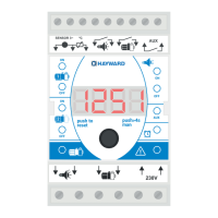
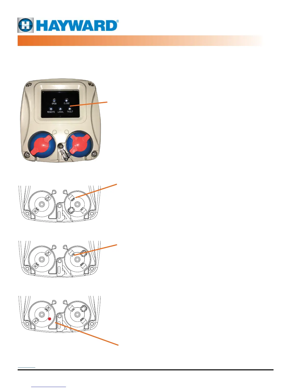
Operating the
Local Control Station
Panel shown in the STOP Mode
Panel shown in the Remote Mode
Panel shown in the Local Mode
driving CLOSED
Panel shown in the Local Mode
driving OPEN
This rectangular NEMA 4X/IP67 (Optional IP68) enclosure houses two non-intrusive
(magnetic) rotary control knobs that provide the user with the ability to operate the
actuator in a normal (REMOTE) mode where the actuator responds to control signals
from a building automation system or a PLC or other control device (by others). Or
the user can elect to operate the actuator in LOCAL mode where one can control
the positioning of the actuator while standing AT the device. This allows opening
and closing the actuator (valve) to test for operation, perform maintenance or other
function without relying on radio communication to command the automation system
to position the actuator.
The panel also contains ve bright LED’s to provide visual indication of the position
and status of the actuator. OPEN (green) and CLOSE (red) ash when the actuator
is MOVING open (CCW) or closed (CW), and they remain steady ON when end of
travel is reached.
The MODE switch (right hand side) has three positions.
• STOP (STOP, On/Off actuators): STOP (center position) removes any ability
to reposition the actuatorelectrically. Power is still present in the unit, and
the OPEN and CLOSE LED indicators are operational. If the unit is fully
CLOSED (CW), then the REDLED will be steady ON. Due to its epicyclic
gear train, the manual handwheelCAN be used to position the actuator. The
actuator will remain in position lastdetermined by the use of the handwheel.
• STOP (STOP, Proportional Control actuators): The actuator generates
a4-20mA(2-10vdc) feedback signal OUT which corresponds to the position
of theactuator.
• REM (REMOTE, On/Off actuators): Sets the actuator to respond to eld
generated control signals. In this mode the POSITION KNOB (left side)
has NO affect on the positioning of the actuator. All actuator movement
is controlled by the external signal device.The manual handwheel may be
used to reposition the actuator while in this mode; however, if an active
external signal is present, the actuator WILLreposition as a function of that
control signal. The LED indicators are activein this mode.
• REM (REMOTE, Proportional Control actuators): The actuator follows
theincoming 4-20mA(2-10vdc) control signal, and generates a 4-20mA(2-10vdc)
feedback signal OUT which corresponds to the position of the actuator.
• LOC (LOCAL, On/Off actuators): Sets the actuator to respond to the
POSITION KNOB (see below).
• The LED indicators are active in this mode.
• All external eld signals are ignored and have no affect on the
positioning of theactuator.
• LOC (LOCAL, Proportional Control actuators): The actuator responds to the
function of the POSITION knob (see below) AND generates a 4-20mA(2-
10vdc)feedback signal OUT which corresponds to the position of the actuator.
The POSITION switch (left hand side) has three positions.
When in the LOC mode, the actuator has been set to respond to the POSITION
KNOB (left side).
• OPE (OPEN, all models): When the POSITION knob is set to OPE, the
actuator will drive to the full CCWposition.
• CLO (CLOSE, all models): When the POSITION knob is set to CLO, the
actuator will drive tothe full CW position.
• There is an unmarked HOLD position detente in theknob (see red dot at
left) that allows the actuator to maintain position at somepoint away from
full travel endstops. In this mode, the manual handwheelmay be used to
reposition the actuator and it will remain in position whilePOSITION knob
is in HOLD. The LED indicators are active in this mode. Allexternal eld
signals are ignored and have no affect on the positioning of theactuator.
There is a padlockable lever that engages with the MODE
knob to lock the operation of the MODE switch in position.
It provides restricted access in any of the three positions.
RECTANGULAR LCS, LED
CL SERIES LCS OPERATION
Back to TOC
 Loading...