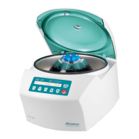
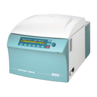
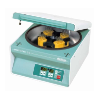
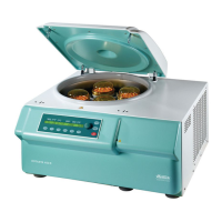
CP : control panel, FC : frequency converter, SB : supply board, CB : cooling board, CC : control cable, LL : lid locking, BC : braking chopper,
BR : brake resistor, MR : mains reset, EC : error cause, ES : error consequence, ER : error remedy, M : measurements, ECR : error-code reset
24/51
• Press
.
key →
Display:
*** OK ***
and then:
PARAM - INIT C001
↑ ↑
machine version
Number of initialisations
• Mains switch is OFF
• Remove both jumpers from slot 3 and slot 4 on coding strip X3 on the CP.
Put a jumper on slot zero at the plug on coding strip X3 on the CP.
(Service position, “Watchdog”)
An initialisation is always necessary
after a replacement of the FC.
5.3. Imbalance Mode
From programme version 3.00 it is necessary to set the imbalance mode during the
initialization.
Depending on the SB version IMBALANCE MODE 1 or IMBALANCE MODE 2 must be
selected.
If the incorrect imbalance mode is selected, the display shows
error "IMBALANCE" permanently !
5.4. OFFSET alignment
An OFFSET alignment is performed to align the temperature sensor and the CP electro-
nics with one another. An alignment must be performed in any event:
− 1. Replacement of the temperature sensor at the centrifuge chamber.
− 2. Replacement of the CP or the EPROM at the CP.
The OFFSET alignment for the temperature sensor is carried out in the CP.
To carry out an offset compensation, measure the temperature directly on the
temperature sensor with a temperature measuring device. Then enter the measured
value in the display and save it.
Each correction must be confirmed by the
.
key.
Requirements: 1. Rotor has stopped.
2. LL is open.
3. Mains switch is OFF.
4. Plug on coding strip X3 at the CP the jumper from slot 0 to slot 3
(OFFSET position).
 Loading...
