50/51
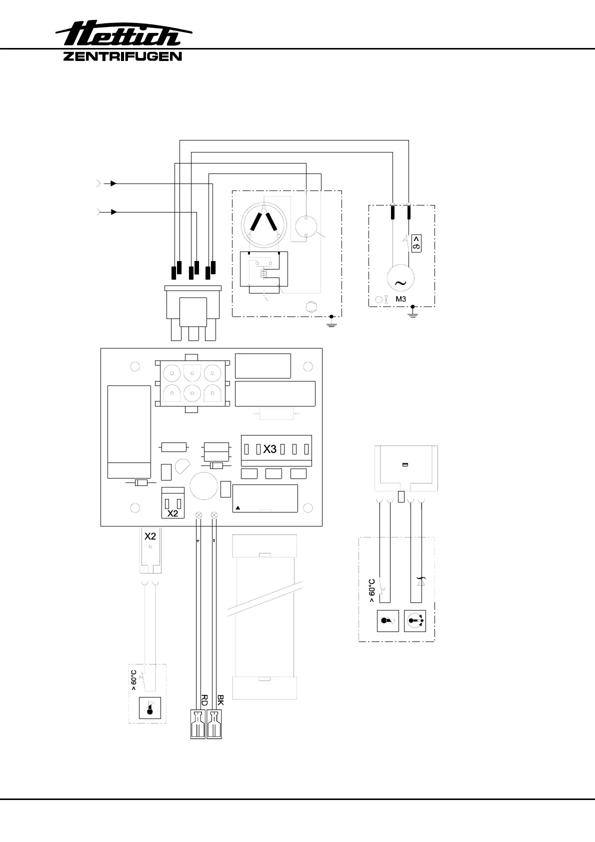
11.11. Connecting diagram and component layout cooling board
BN
WH
GN
YE
1
2
3456
Temperaturfühler und Über-
temperaturschalter im Kessel
temperature sensor and overtemperature
switch in centrifuge chamber
B1
12
WH or GN or GY
BN or YE or PK
6
2
3
5
1
4
zur Versorgungsplatine A1
to suppl
board A1
zum Steuerteil A4
to control panel A4
A4 / X101
A3 / X4
X8
X7
X3
Anlaufkondensator
startup condenser
Motorschutzschalter
motor protective switch
2
SM
12
AP
C
1
1
3
M2
WH
BK
X1
BK
WH
M
14
5
6
2
3
C1
VDR1
R1
C6 C4 C5
X1
C3
X4
R2R3
R4
D1
C2
+
1
1
C7
T1
REL1
D2
1
vom Funkentstörfilter Z1 (230 V )
von Netzschalter Q1 (115 V )
from radio inference suppression filter Z1 (230 V model
from mains switch Q1 (115 V model)
Ausführung
Ausführung
Z1 / 2
Q1 / 3
Z1 / 1
Q1 / 4
B2
Übertemperaturschalter im Kühlsystem
overtemperature switch in cooling system
 Loading...