CP : control panel, FC : frequency converter, SB : supply board, CB : cooling board, CC : control cable, LL : lid locking, BC : braking chopper,
BR : brake resistor, MR : mains reset, EC : error cause, ES : error consequence, ER : error remedy, M : measurements, ECR : error-code reset
8/51
2.3. Supply board (SB) A1
The SB performs the following individual functions:
• 12 V DC and 5 V DC supply for the SB.
• 12 V DC supply for the CP.
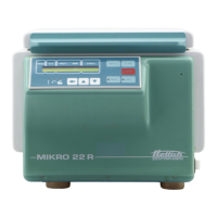
• 12 V DC supply for the CB (only Mikro 22 R).
• Plugging station X5 for mains power supply, LL magnet and transmission of the
signalling circuit for LL switch (open/closed over opto-coupler to the CP).
• Power supply for speed sensor (speedometer).
• Plugging station X4 for speed sensor cable and transmission to the CP and FC.
• Control of the relay for the LL solenoid at rotor standstill
• Plugging station X3 for the imbalance switch and direct transmission of the imbalance
signal to the CP.
• The 5 Volt interface with 3 conductors is converted to an RS 485 interface with 2
conductors:
Interface to FC: RS 485-interface via 2 conductors -
• Transfer of primary enabling (=Hardware STOP) CP ⇒ FC
• Transfer of fault circuit (=FC-ERROR) FC ⇒ CP
2.4. Frequency converter (FC) A2
The FC performs the following individual functions:
• Generation of the motor power supply
(3-phase AC current of variable frequency and voltage)
Mode of operation: The mains supply is rectified, smoothed and chopped in three
bridge elements to give a pulse-duration modulated supply.
• Monitoring of the motor current
• Evaluation of the overtemperature switch in the motor (only version 115V, AC)
• Slave behaviour (handling of interrogations and commands from the CP via the serial
interface):
RS 485-interface with 2 conductors
(10-pole control cable, pole 3 and 5)
• Evaluation of the primary enabling (=Hardware STOP) for the FC
(10-pole control cable, pole 7)
• Evaluation of potential faults and monitoring of the fault circuit (=FC-Error)
(10-pole control cable, pole 4)
• The electrical power, which resulted from braking, will be conducted to the BR. The
braking chopper switches at a voltage:
- from approximately 390V (230V series)
- from approximately 200V (115V series)
• The BR is protected by an overtemperature switch. At a short circuit on the BC,
which is located on the FC, the BR overheats because of high current. The
overtemperature switch cuts off the voltage supply from the FC. After cooling down at
the BR the voltage supply is switched on again.
 Loading...
