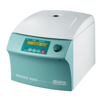
CP : control panel, FC : frequency converter, SB : supply board, CB : cooling board, CC : control cable, LL : lid locking, BC : braking chopper,
BR : brake resistor, MR : mains reset, EC : error cause, ES : error consequence, ER : error remedy, M : measurements, ECR : error-code reset
30/51
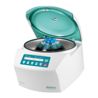
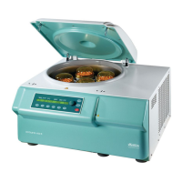
8. Functional test
8.1. Checking the proper working order
By measuring and comparing the data listed under Table 7, it can be determined if a
centrifuge is in proper working order. A precondition for this is that the necessary
components stated under Table 7 are used for the measurements.
If the measurements are carried out using other components, the numerical values from
the ”Rotor and accessories” chapter of the operating instructions for the particular cen-
trifuge must be employed.
If the measured values obtained for:
• the speed,
• the starting and rundown times
• the temperatures in cooled centrifuges,
are identical to the numerical values in Table 7, or to those in the ”Rotor and accesso-
ries” section of the operating instructions, then the centrifuge is in proper order.
8.2. Proper working order after repairs
See section headed ”Checking the proper working order”. The following values must be
checked in addition:
• Insulation resistance > 2 MΩ
• Protective conductor resistance < 0,2 Ω
• Leakage current
< 3,5 mA *
* limit according to EN 61010
A laboratory centrifuge do not belong to those medical appliances which may be tested
according to the regulation IEC 601 or corresponding national medical electronic
standards. Laboratory centrifuges are classified as laboratory equipment.
The regulations applying to laboratory equipment are IEC 1010 or European standard
EN 61010.
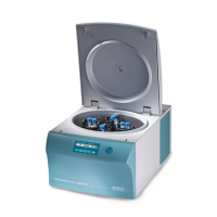
9. Assembling and disassembling components
Before assembling or disassembling components, the working processes in Table 9-B
for MIKRO 22 and MIKRO 22 R must first be carried out to reach the components and
make a note of the plug numbers.
The components are assembled in reverse order !
The further procedure is described on the following pages.
 Loading...