CP : control panel, FC : frequency converter, SB : supply board, CB : cooling board, CC : control cable, LL : lid locking, BC : braking chopper,
BR : brake resistor, MR : mains reset, EC : error cause, ES : error consequence, ER : error remedy, M : measurements, ECR : error-code reset
33/51
9.1. Speed sensor B3 (speedometer)
• Unscrew speed sensor (speedometer) from upper end plate of motor.
• Unplug plug number X4 from Supply board A1.
• Replace speed sensor (speedometer).
9.2. Motor M1 / Vibration damper
• Unscrew speed sensor (speedometer) from upper end plate of motor, and place it in
centrifuge chamber.
• Pull out the 3 cables from plug S101 at the FC (BU/BN/BR).
• Use a socket spanner to loosen and remove the three fastening nuts on lower end
plate of motor.
• Lift motor upwards out of centrifuge. Unplug the earth lead.
• Before motor is installed, the three vibration dampers must be checked for possible
wear or cracks, and if necessary replaced.
• Replace the motor.
• Care must be taken of the anti-twist device when the vibration dampers are being
installed.
9.3. FC (frequency converter)
• Pull all plugs out of FC.
• Unscrew the four fastening screws of FC.
• Unscrew the screws on the connecting clips and pull the cables out.
• Replace FC
• Before installation, it must be noted that there is a heat-conducting paste between FC
and centrifuge housing floor.
Heat conducting from FC to centrifuge housing floor must be ensured.
9.4. SB (supply board) A1
• All plugs on the SB must be pulled out.
• Unscrew the four screws, and take SB out of centrifuge.
• Replace SB
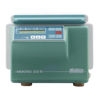
9.5. CB A3 (cooling board) only MIKRO 22 R
• All plugs on the CB must be pulled out.
• Unplug the two cables (RD and BK) at the SB.
• Unscrew the four fastening screws at the CB.
• Replace the CB.
 Loading...
