CP : control panel, FC : frequency converter, SB : supply board, CB : cooling board, CC : control cable, LL : lid locking, BC : braking chopper,
BR : brake resistor, MR : mains reset, EC : error cause, ES : error consequence, ER : error remedy, M : measurements, ECR : error-code reset
7/51
2. Description of the new Hettich centrifuges
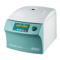
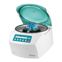
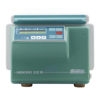
2.1. Functional structure of the Mikro 22 / 22 R
These microprocessor-controlled centrifuges are comprised of the following electrical
components:
• Control panel (CP), microprocessor-controlled
• Supply board (SB)
• Frequency converter (FC, motor control), microprocessor-controlled
• Motor with speed sensor (speedometer)
• Braking chopper (BC) with brake resistor (BR)
• Lid locking (LL)
• Cooling board (CB), only Mikro 22 R
2.2. Control panel (CP)
The CP is the ”brain” or ”master” of the centrifuge.
Via a serial data bus system, the MASTER controls its SLAVE, the component:
− frequency converter (FC)
The individual tasks of the CP are:
• Management of operator inputs and control of LCD display
• Storage of 3 run programs
• Control of components:
− FC via the enabling circuit and via the serial interface
− cooling and fan
• Evaluation of the speed sensor (speedometer)
• Evaluation of the imbalance switch.
• Evaluation of the FC fault alarm circuit
• Evaluation of the LL open/closed signalling circuit
• Control of the relay for the LL solenoid at rotor standstill
• Temperature measurement and sensor evaluation of the temperature sensor in
centrifuge chamber (only refrigerated centrifuge).
• Routine for input, storage and transfer of temperature offset values
• Format of the serial interface:
5 Volt interface with 3 conductors
(16-pole control cable, pole 6, 8 and 11)
• The CP is powered from the SB via the control cable:
+ 10...15 Volt pole 1,2
GND pole 15,16
 Loading...