Chapter 3. Wiring and Signals
3-11
3.2.4 Analog I/O signal
Analog signal is based on 0 [V] (GND terminal) of the control power supply. Connect the GND
terminal of the circuit connected to this signal with the GND terminal of CN1. The analog speed
command input (CN1-27) runs the motor at a speed determined from the 10V Speed [RPM] (P3-16)
menu of Speed Mode (P3- ). Regardless of input voltage polarity, only plus value is applied.
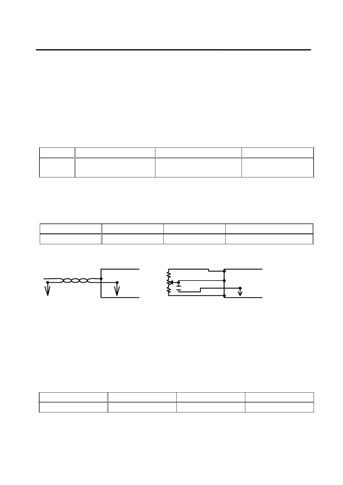
To wire analog signals, connect GND wire with the signal wire by twisting them using twist pair wire
in order to minimize noise. Functions of each analog signal are as follows.
Pin Name SPDIN ( 27 ) MONIT1 ( 3 ) MONIT2 ( 2 )
Signal
function
Speed command
-10∼+10 [V] input
Monitor output 1
-4∼+4 [V] output
Monitor output 2
-4∼+4 [V] output
Analog signal is based on GND signal, and produces ±12 [V] power just in case speed commands
are applied through the use of variable resistance. The output capacity of this power supply is 30
[mA] at maximum. Do not exceed the maximum capacity. The power supply pin array is shown on
the following table.
Pin Name + 12 V ( 35 ) - 12 V ( 37 ) GND (1,8,26,33,34,36)
Signal function + 12 [ V ] - 12 [ V ] 0 [ V ]
3.2.5 Encoder output signal
The encoder signal is produced based on 0 [V] (GND) of control power supply. Connect 0 [V]
terminal of the circuit which receives this signal from the master control system to the GND terminal
of CN1. Encoder signal is produced in line driver system after the AC servo motor encoder signal
received from CN2 is divided according to the frequency dividing ratio set by the sub-menu Pulse
Out Rate (P2-06) of the main menu Control Mode (P2-). Function of each signal is as follows.
Signal function A phase output B phase output Z phase output
PIN No(CN1-) PAO(7)/PAO(32) PBO(6)/PBO(31) PZO(5)/PZO(30)
GND
[Analog signal connection]
Driver
SPDIN
TWIST
PAIR
peed command
1/2W 220
2K
1/2W 220
104
GND
Driver
SPDIN
[Using the internal power for the analog command]
-12
+12

 Loading...