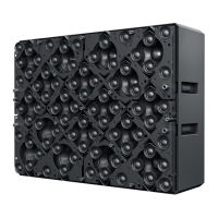
31X1 MD80-S Manual 1.0 en
Network Cables
• Each HOLOPLOT Audio Module must be connected
with at least one direct Gigabit copper-based network
connection for conguration and maintenance.
• All copper cables must be CAT6-rated.
• All cables should be strain-relieved.
• For connectors and cable dress, there must be at least
100 mm clearance on the back of an Audio Module.
Network Setup and Requirements
Color-coded cabling should be used
to reduce uncertainty in maintenance.
i
All HOLOPLOT devices in one
VLAN/subnet form a single
HOLOPLOT System. If you want
to separate multiple systems
(e.g. having a system for testing/
production and a system for
operation), each system must be
networked in its own VLAN/subnet.
Devices of different systems cannot
live in the same VLAN/subnet of a
network.
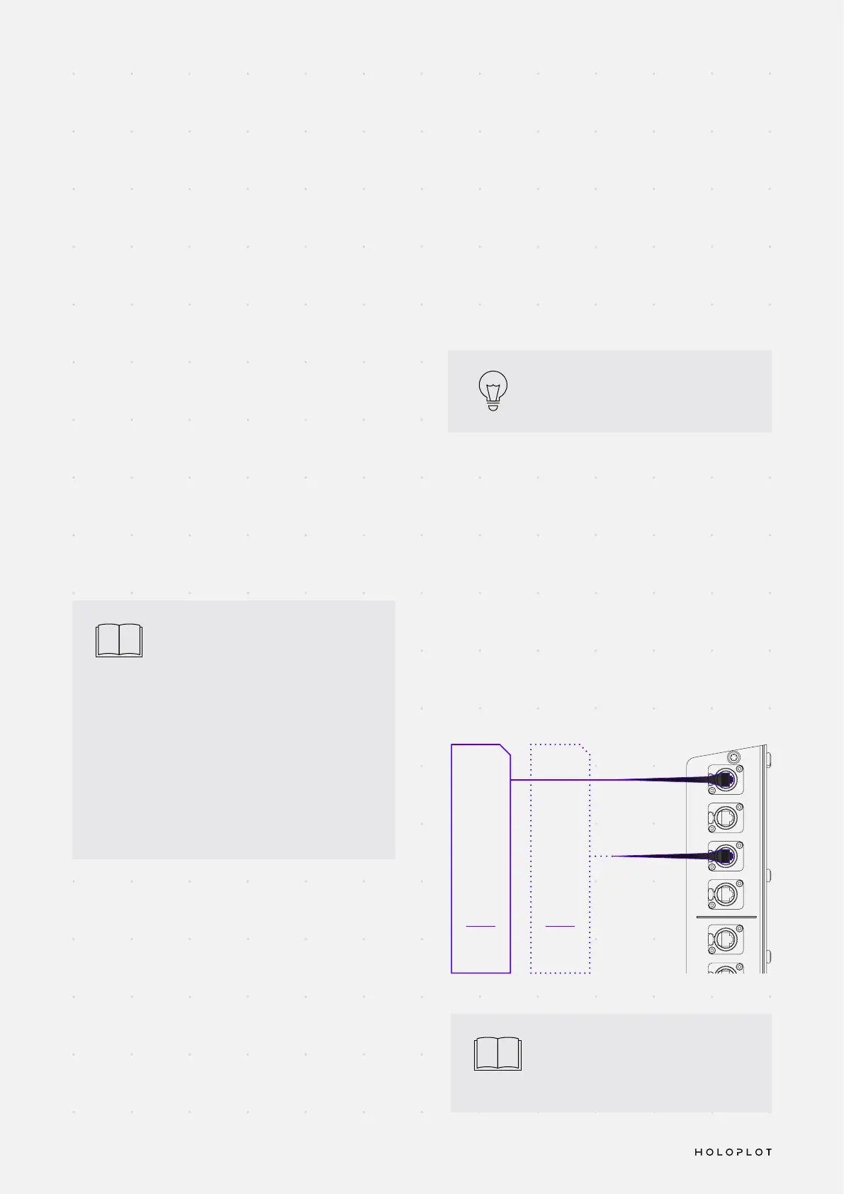
NETWORK CABLE CONNECTIONS
Practically, one Ethernet line is run from each switch to
an Audio Module, occupying two networking ports on
the Audio Module: the primary switch connects to the
Primary Uplink port and the secondary switch connects
to the Secondary Uplink port.
i
The maximum CAT6 cable length
supported for control and Dante
audio networking is 100 meters.
NETWORKING REQUIREMENTS
Networking appliances
• A DHCP server needs to be present to provide all
Audio Modules and HOLOPLOT Controller(s) with IP
addresses. The HOLOPLOT System does not work
with static IP addresses.
• To achieve full network redundancy, the network
switches must be laid out in a redundant manner.
• Distribution switches should be located in close
proximity to the Audio Modules, and cable length
must not exceed 100 meters.
• All network switches must be compatible with the
Audinate Dante networking technology.
Network conguration
• All HOLOPLOT devices of one system must be
networked in the same VLAN.
• In case of other devices on the same network, VLANs
should be used in order to separate the trafc on
layer 2 logically.
Network
Secondary
Switch with
DHCP
Server
K
R
O
W
T
E
N
Secondary
Uplink
Secondary
Downlink
Primary
Downlink
Primary
Uplink
K
N
I
L
O
L
O
H
A
B
1
2
K
N
I
L
B
U
S
N
I
Do not connect
under load
T
U
O
AC Output:
240V
~
9.5A
208V
~
9A
AC Input Range:
115-240V
50-60Hz
AC Input:
115V
~
6.5A
240V
~
12.8A
Network
Primary
Switch with
DHCP
Server
 Loading...