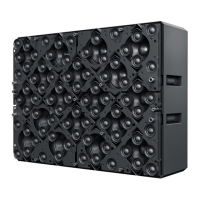
32X1 MD80-S Manual 1.0 en Network Setup and Requirements
Secondary
Downlink
K
N
I
L
O
L
O
H
A
B
1
2
K
N
I
L
B
U
S
N
I
Do not connect
under load
T
U
O
AC Output:
240V
~
9.5A
208V
~
9A
AC Input Range:
115-240V
50-60Hz
AC Input:
115V
~
6.5A
240V
~
12.8A
AC Input Range:
115–240 V
50–60 Hz
AC Input:
115 V
~
1.1 A
240 V
~
0.9 A
Do not connect
under load
Only power from
Electronics Package
at Power
IN ≥ 208 V
SUBLINK
IN
PROVIDING SIGNAL TO THE
SUBWOOFER VIA SUBLINK
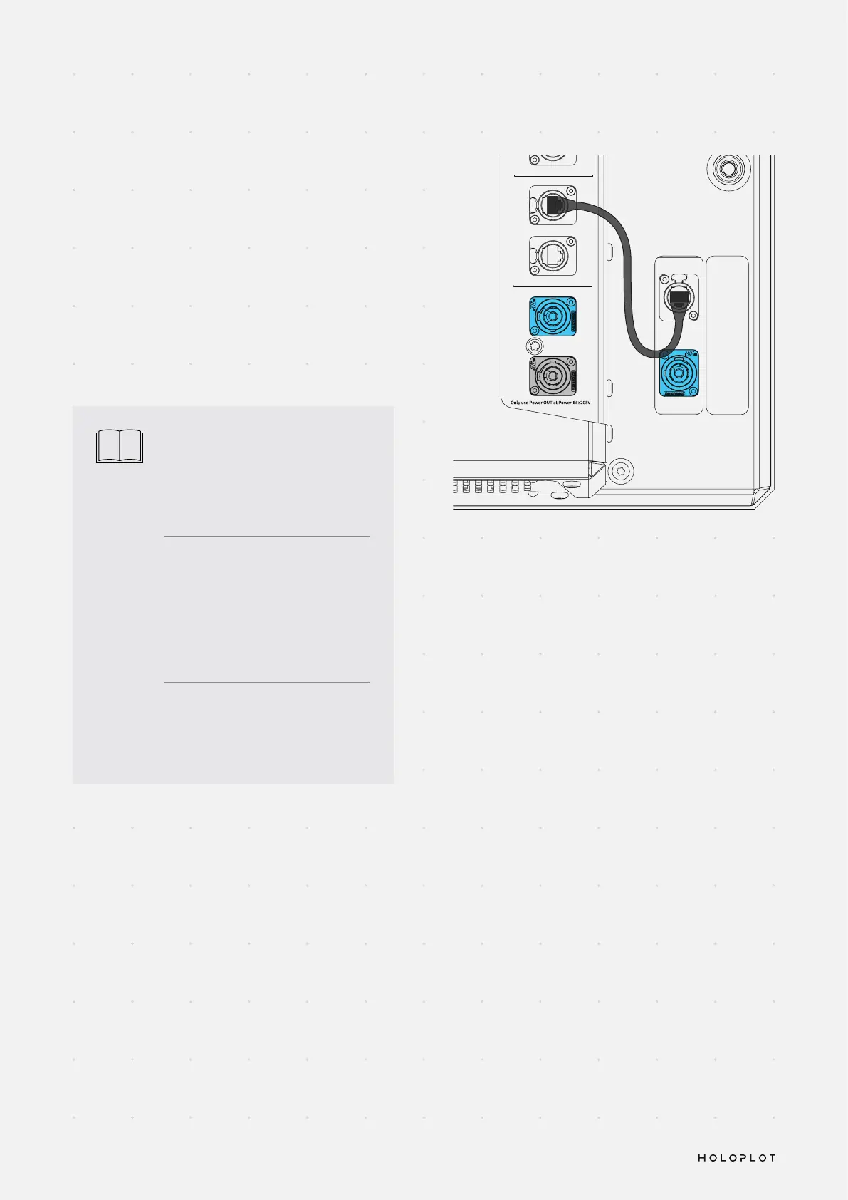
The Loudspeaker Cabinet of the MD80-S integrates an
additional power supply and amplier for the subwoofer
driver. To provide audio and control signal to this
subwoofer amplier module, connect the SubLink 1
connection (on the connector panel of the Electronics
Package) to the SubLink IN port (on the connector panel
of the Loudspeaker Cabinet).
The SubLink port may also be used to provide audio and
control signal to standalone Subwoofer Modules offered
by HOLOPLOT in the future.
i
To connect the SubLink 1 port on the
Electronics Package to the SubLink
In port on the Loudspeaker Cabinet,
use the dedicated SubLink cable
shipped with the MD80-S.
The physical SubLink connection
using the CAT6 cable between
the Electronics Package and the
subwoofer amplier module needs
to be established before powering
up the Audio Module.
The maximum CAT6 cable length
supported by SubLink is 15 meters.
 Loading...