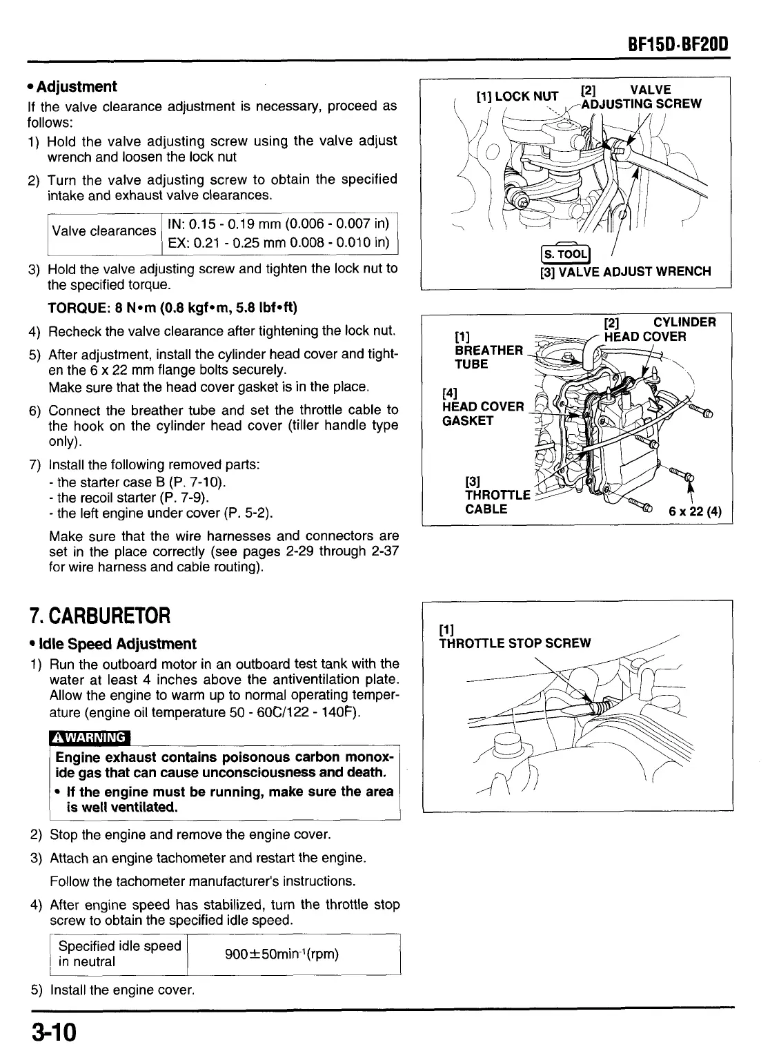
Adjustment
If the valve clearance adjustment is necessary, proceed as
follows:
1) Hold the valve adjusting screw using the valve adjust
2) Turn the valve adjusting screw
to
obtain the specified
wrench and loosen the lock nut
intake and exhaust valve clearances.
IN:
0.15
-
0.19 mm (0.006
-
0.007 in)
EX:
0.21
-
0.25
mm
0.008
-
0.010 in)
Valve clearances
3)
Hold the valve adjusting screw and tighten the lock nut to
the specified torque.
TORQUE:
8
N*m
(0.8
kgf*m,
5.8
Ibf*ft)
4)
Recheck the valve clearance after tightening the lock nut.
5)
After adjustment, install the cylinder head cover and tight-
en the
6
x 22
mm
flange bolts securely.
Make sure that the head cover gasket is in the place.
6) Connect the breather tube and set the throttle cable
to
the hook on the cylinder head cover (tiller handle type
only).
-
the starter case
B
(P.
7-10).
-
the recoil starter
(P.
7-9).
-
the left engine under cover
(P.
5-2).
Make sure that the wire harnesses and connectors are
set in the place correctly (see pages 2-29 through 2-37
for wire harness and cable routing).
7) Install the following removed parts:
7.
CARBURETOR
Idle Speed Adjustment
1) Run the outboard motor
in
an outboard test tank with the
water at least
4
inches above the antiventilation plate.
Allow the engine to warm up to normal operating temper-
ature (engine oil temperature
50
-
60C/l22
-
140F).
If
the engine must be running, make sure the area
is
well ventilated.
2) Stop the engine and remove the engine cover.
3)
Attach an engine tachometer and restart the engine.
Follow the tachometer manufacturer's instructions.
4)
After engine speed has stabilized, turn the throttle stop
screw
to
obtain the specified idle speed.
(s.]
I
[3]
VALVE ADJUST WRENCH
[2]
CYLINDER
HEAD COVER
11
1
THROTTLE
STOP
SCREW
5)
Install the engine cover.
3-1
0
 Loading...